Brazed component and method of forming a brazed joint therein

a brazed joint and component technology, applied in the field of brazing, can solve the problems of weakening the brazed joint, improper wetting, and affecting the strength of the brazed joint, so as to reduce the capillary force of the brazed material and reduce the flow of material

Active Publication Date: 2014-06-17
SKN SINTER METALS LLC (US)
View PDF9 Cites 2 Cited by
  • Summary
  • Abstract
  • Description
  • Claims
  • Application Information

AI Technical Summary

Benefits of technology

[0027]In another form, the flow control feature may be a lip that locally increases the inter-component gap between the first component and second component. The lip may inhibit a capillary action of the brazing material during the brazing process.
[0030]In still yet another form, the flow control feature may be a lip formed between two sections of the inter-component gap that are not in the same plane as one another. The lip reduces a capillary force of the braze material proximate the flow control feature to reduce the flow of material from one of the two sections to the other.
[0031]In still yet another form, the flow control feature may be configured to stop the progression of a meniscus of the brazed material in liquid form past the flow control feature during the brazing process by locally increasing the inter-component gap
[0032]Thus, a brazed part and methods related to forming a brazed part are provided that solve many of the aforementioned problems associated with brazing. Using the structures and methods described herein, it is possible to locate two or more components relative to one another in a manner that provides a uniform and consistent gap between the surfaces. As the joints are self-locating, some mishandling of the parts will not upset the positioning of the parts relative to one another. This minimizes the likelihood of the gap increasing to the point at which capillary action of the brazing material is insufficient to entirely fill the gap, potentially resulting in the localized overflow of the brazing material while in liquid form. Further, the flow control features and method of controlling the flow of the brazing material help to retain all of the brazing material in the gap and allow for brazements having complex geometries that would be otherwise difficult, if not impossible, to achieve without such use of such flow control features.

Problems solved by technology

The strength of the brazed joint may be compromised if the brazing surfaces are not properly wetted by the brazing material.
Improper wetting may occur if the distance between the surfaces to be brazed is irregular or if there is not enough brazing material to fill the gap between the components.
If the brazing material does not completely fill the gap between the components, then this defect weakens the brazed joint and makes it more susceptible to mechanical failure.
Such misalignment can alter the uniformity and the consistency of the spacing of the components, adversely affecting the wetting of the surfaces during brazing and creating the potential for loss of some of the brazing material via overflow.
Further, if mishandling has severely misaligned the components, then the overall dimensional requirements for the final brazed part may not be met, meaning that the part will need to be scrapped or subjected to costly post-brazing secondary operations.

Method used


Image

  • Brazed component and method of forming a brazed joint therein
  • Brazed component and method of forming a brazed joint therein
  • Brazed component and method of forming a brazed joint therein

Examples


Embodiment Construction

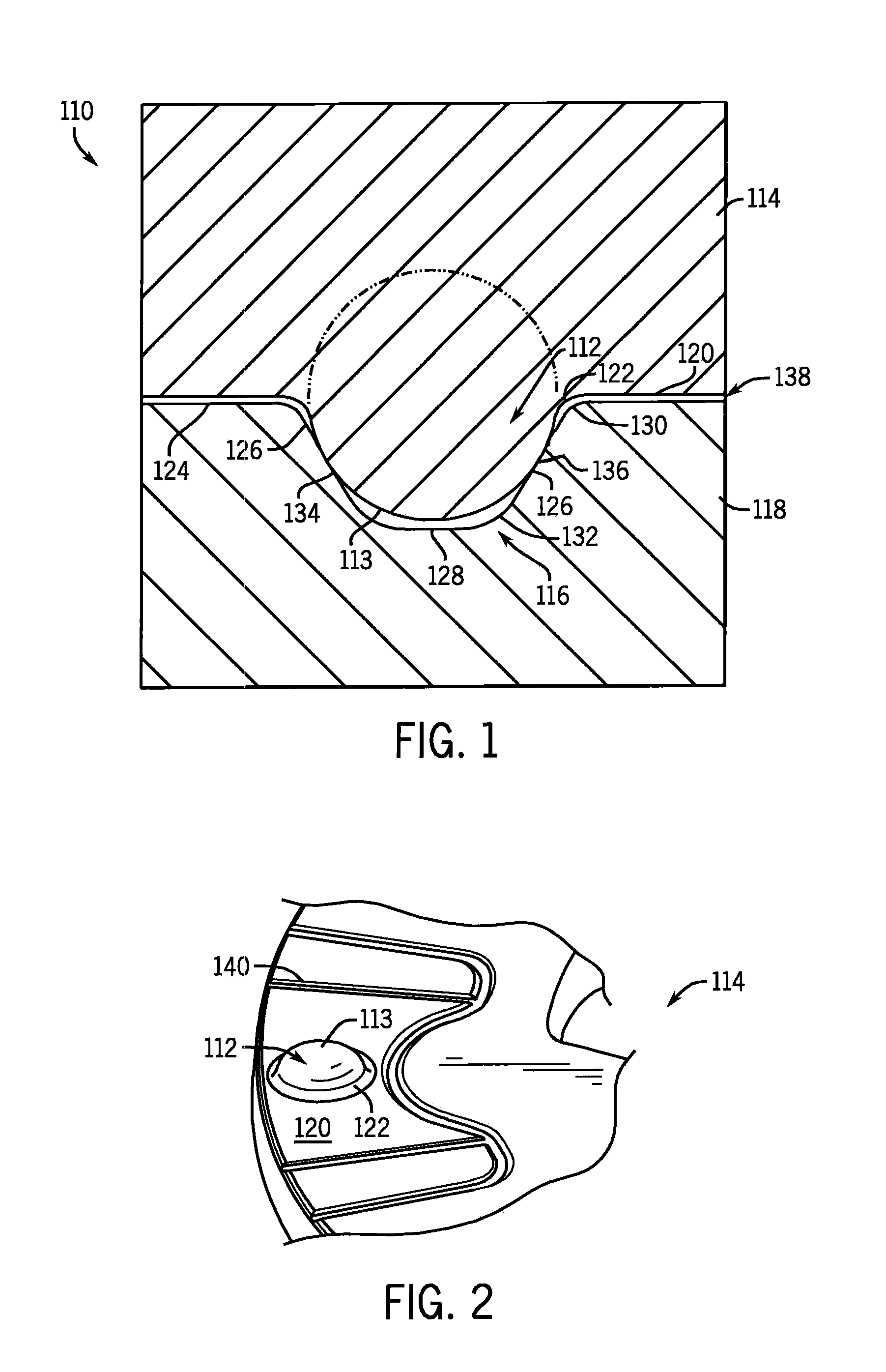
[0048]Referring now to FIG. 1, a locating joint 110 is shown. The locating joint 110 includes a projection 112 having an arcuate convex surface 113 on a first component 114 and a recess 116 on a second component 118.

[0049]Referring now to FIGS. 1 and 2, the projection 112 extends from a surface 120 of the first component 114 and may include a transitioning radius 122 between the surface 120 and the arcuate convex surface 113. It should be appreciated that the arcuate convex surface 113 may have other surface geometries including, but not limited to, a semi-spherical surface having a constant radius. The projection 112 may be referred to as the male mating component or by other similar terms.

[0050]Referring now to FIGS. 1 and 3, the recess 116 extends into a surface 124 of the second component 118 and includes opposite-facing angled walls 126 extending down to a bottom 128 of the recess 116. Like the projection 112, the recess 116 may have transitioning radii 130 and 132 between the ...


PUM

PropertyMeasurementUnit
capillary forceaaaaaaaaaa
distanceaaaaaaaaaa
rotational stressaaaaaaaaaa

Abstract

A brazed part, and methods of forming a brazed joint therein, are disclosed. The brazed part includes two or more components that are brazed together. Using the method of locating the parts herein disclosed, an inter-component gap between the components may be formed. Flow control features formed along the inter-component gap may then be used to assist in the retention of the braze material between the components during brazing.

Description

CROSS REFERENCE TO RELATED APPLICATIONS[0001]This application represents the national stage application of International Application PCT / US2009 / 034697 filed Feb. 20, 2009, which claims the benefit of U.S. provisional application Ser. No. 61 / 066,804 entitled “Locating Joint and Method of Locating” filed on Feb. 22, 2008 and U.S. provisional patent application Ser. No. 61 / 101,457 entitled “Braze Flow Control” filed on Sep. 30, 2008, the entire contents of which are incorporated herein by reference in their entirety for all purposes.STATEMENT OF FEDERALLY SPONSORED RESEARCH OR DEVELOPMENT[0002]Not applicable.BACKGROUND OF THE INVENTION[0003]This disclosure relates to the brazing of two or more components. In particular, this disclosure relates to component structures for controlling the flow of brazing material between the components and methods related to forming and using said structures to provide stronger brazements between the components.[0004]Brazing is a process by which two or ...

Claims


Application Information

Patent Timeline
Patent Type & Authority Patents(United States)
IPC IPC(8): B23K33/00B23K1/00
CPCB23K1/0008B23K33/00Y10T428/12389Y10T428/1241B23K1/20Y10T403/1624
Inventor LEMKE, JEFFREY W.DONALDSON, IAN W.GUROSIK, JOHN DAVID S.
Owner SKN SINTER METALS LLC (US)
Why Eureka
Try Eureka