Actuating device

a technology of actuating parts and actuators, which is applied in the direction of operating means/releasing devices of valves, magnetic bodies, brake systems, etc., can solve the problems of relatively complex guidance of the actuating part within the pole core, and high implementation costs, and achieve the effect of low production costs

Inactive Publication Date: 2014-06-24
HYDAC ELECTRONICS GMBH
View PDF14 Cites 4 Cited by
  • Summary
  • Abstract
  • Description
  • Claims
  • Application Information

AI Technical Summary

Benefits of technology

[0005]An object of the invention is to provide an improved actuating device maintaining the prior art advant...

Problems solved by technology

In spite of these advantages, the known solution, with respect to the guidance of the ac...

Method used


Image

  • Actuating device
  • Actuating device
  • Actuating device

Examples


Embodiment Construction

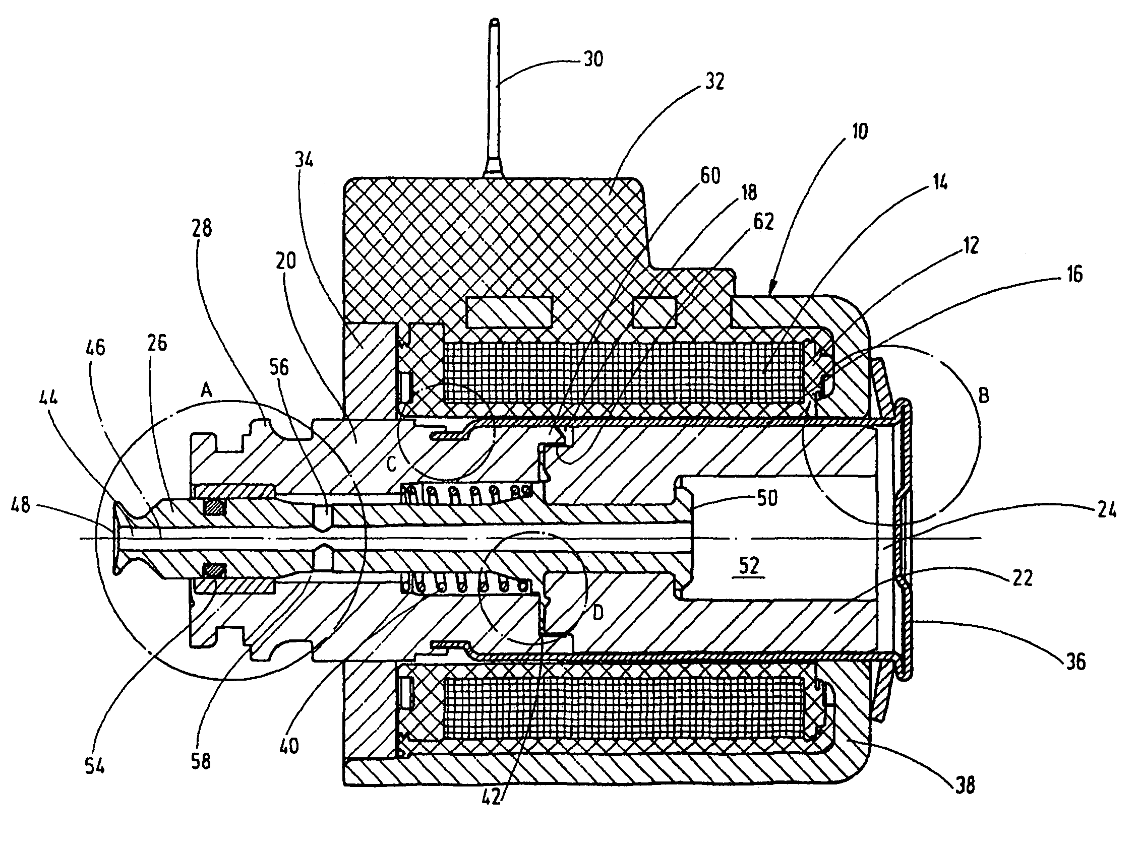
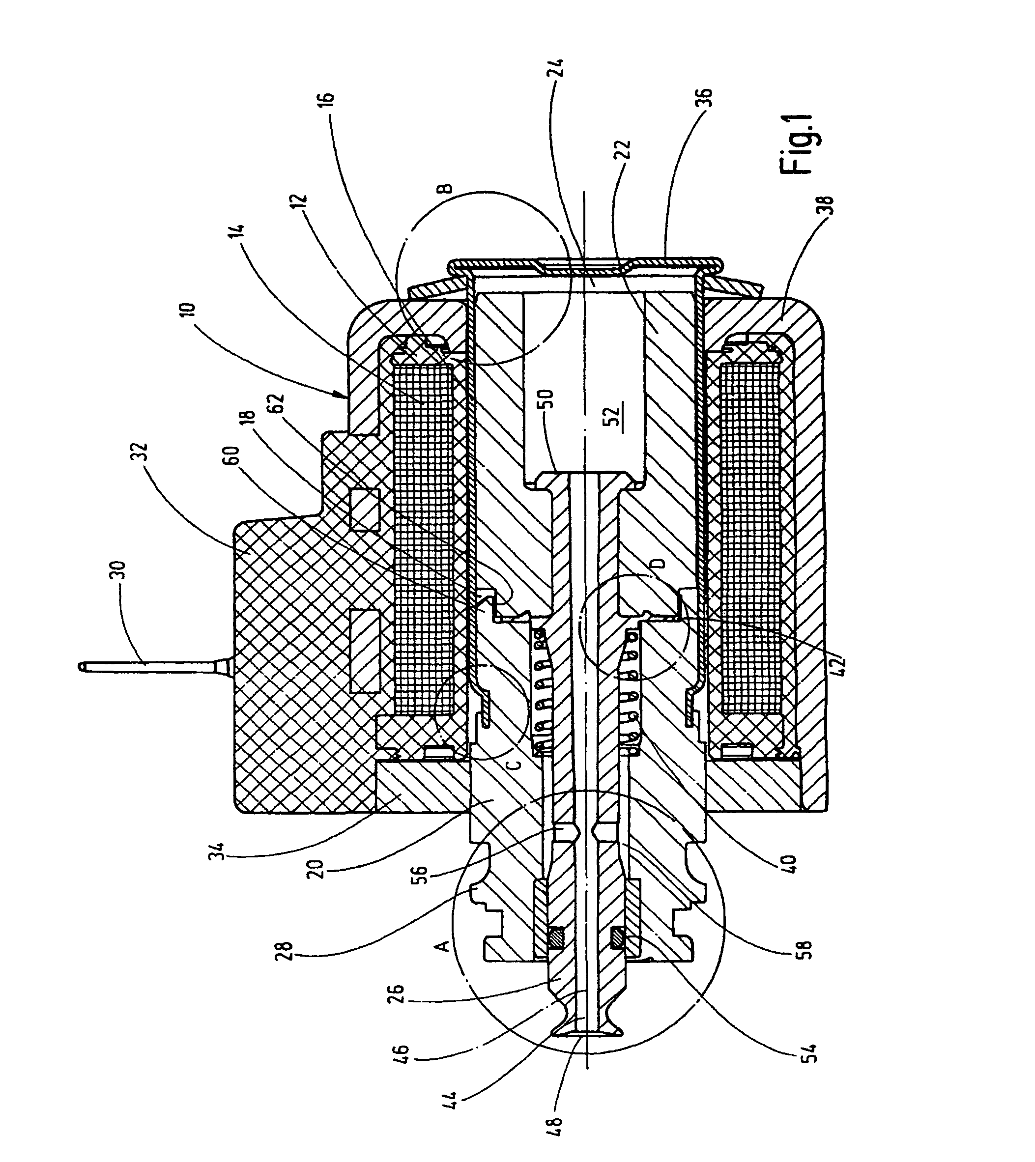
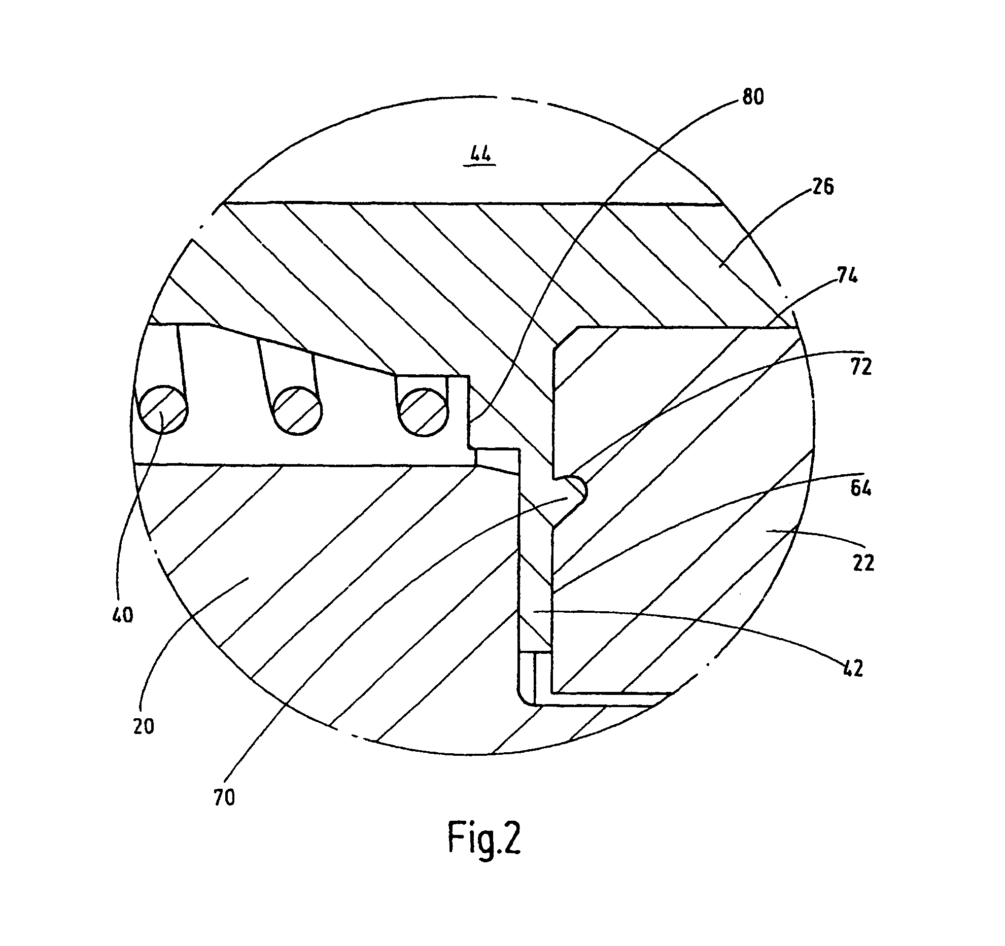
[0032]The actuating device which is shown in a longitudinal section in FIG. 1 and which is also referred to as an “actuating or switching magnet” has a housing 10 with a coil body 12 located therein with a coil winding 14. This coil body 12 comprises at least in part a pole tube 16 which is essentially magnetically decoupled from a pole core 20 by a point of separation 18 in the form of a site which is left open. The prior art also discloses solutions (not shown) in which a corresponding point of separation is formed by a weld or the like. Along the pole tube 16 an armature 22 is guided to be longitudinally displaceable in an armature space 24 which on its one free, front end interacts with a rod-shaped actuating part 26 for actuating fluid valves (not shown) of conventional design, especially in the form of pneumatic valves which are not detailed. To connect this valve, the pole core 20 on its free end is provided with a connecting flange 28. The connecting flange 28 on its outer p...


PUM


Abstract

An actuating device, particularly for actuating valves that can be connected externally, includes a housing (10) and a coiled body (12) in the housing and having a coil winding (14). The winding encloses a pole tube (16) at least partially, having a pole core (20) connected at its free end. An armature (22) is guided in a longitudinally displaceable manner at least in the pole tube (16) within an armature chamber (24) and interacts with an actuating device (26) for actuating a valve part. The actuating part (26) is guided within the pole core (20) along an annular body (92), sealing the inside of the pole core (20) and the pole tube (16) relative to the surrounding area.

Description

FIELD ON THE INVENTION[0001]The invention relates to an actuating device, in particular for actuating valves that can be connected externally, comprising a housing and a coil body arranged therein and having a coil winding. The coil body encloses at least in part a pole tube to whose one free end a pole core is connected. An armature is guided to be longitudinally displaceable at least in the pole tube within an armature space and interacts with an actuating part for actuating the respective valve part.BACKGROUND OF THE INVENTION[0002]These actuating devices, which are also referred to as “actuating or switching magnets” are described, for example, in DE 101 04 998 A1 and are readily available on the market in a plurality of embodiments. The actuating part of the actuating magnet is essentially formed from a tubular pin which traverses a definable path when the coil winding is electrically excited by a connector socket which can be connected to the attachment plug plate. In doing so...

Claims


Application Information

Patent Timeline
IPC IPC(8): F16K31/02
CPCH01F7/1607F16K31/0693H01F2007/163H01F2007/1661
Inventor BILL, MARTINLAUER, FLORIAN
Owner HYDAC ELECTRONICS GMBH
Why Eureka
Try Eureka