
Optical connector assemblies having alignment components

a technology of optical connectors and assembly parts, applied in the field of optical cable assemblies and optical connector subassemblies, can solve the problems of insufficient ruggedness for consumer electronics applications, inability to meet the requirements of high-speed data transmission, so as to avoid or reduce coupling loss. the effect of facilitating data transmission

Inactive Publication Date: 2014-06-24
CORNING OPTICAL COMM LLC
View PDF3 Cites 71 Cited by
  • Summary
  • Abstract
  • Description
  • Claims
  • Application Information

AI Technical Summary

Benefits of technology

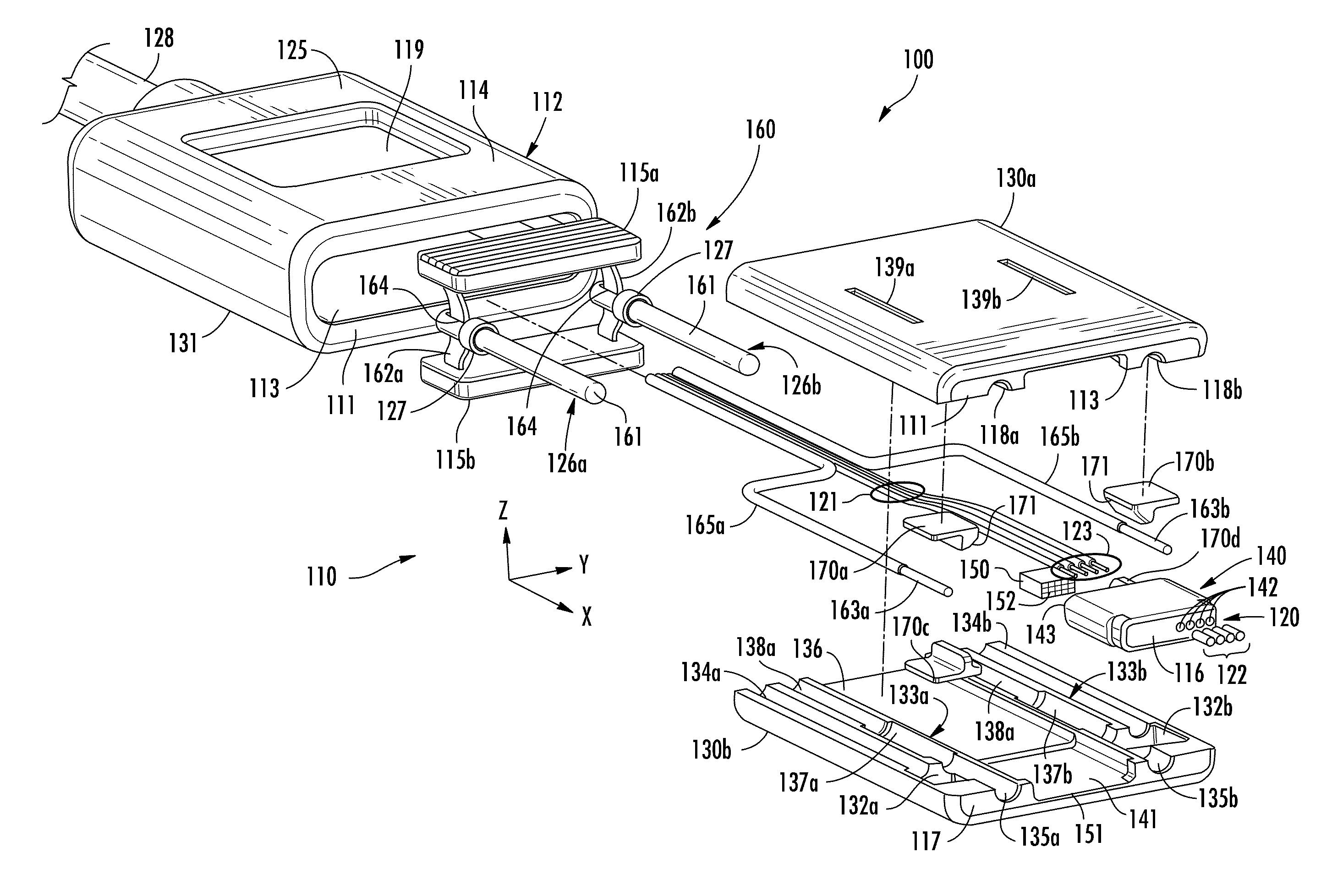
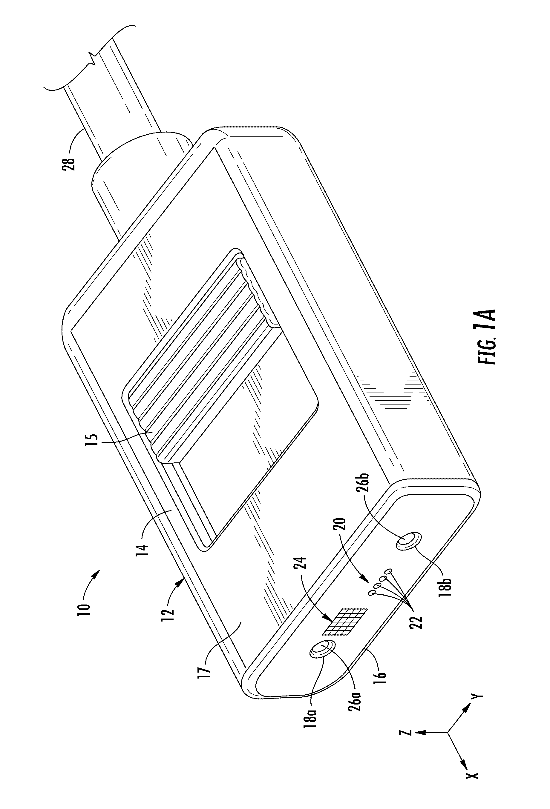
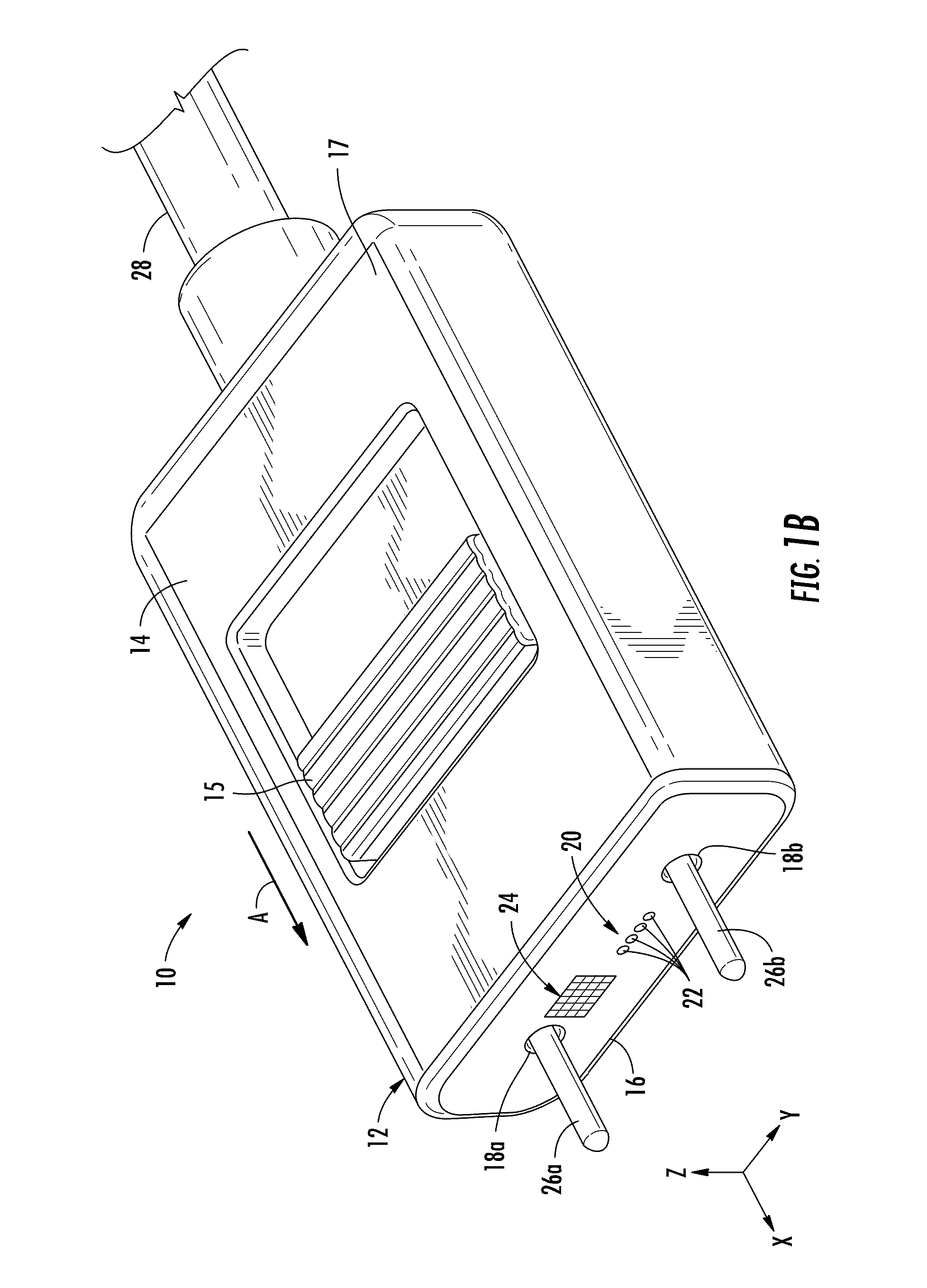
The patent text describes a cable assembly and optical connectors that use optical fibers for data transfer. The text explains the importance of precise alignment between the end faces of the optical fibers and the optical device or other optical fiber to avoid coupling loss. The text also mentions the use of lenses, such as gradient index lenses, to simplify multiple optical fiber connections. The lenses can be provided in a glass rod form and easily bonded or fused to the optical fibers. The optical connector has an access surface that is easy to clean and is free from mechanical structures. The text also mentions the use of retractable alignment pins and coded magnetic arrays for coarse and fine alignment with the mated optical connectors. The technical effects of this patent are to simplify the optical fiber connection process and improve the connection's reliability.

Problems solved by technology

As such alignments require tight tolerances, the mechanical structures become costly, and may not be rugged enough for consumer electronics applications.
Further, the mechanical structures often cause the optical interface of the optical cable assembly and the electronics device to be susceptible to the build-up of foreign substances (e.g., dust, liquid, food particles, etc.) that may interfere with the propagation of optical signals between the optical cable assembly and the electronics device.

Method used


Image

  • Optical connector assemblies having alignment components
  • Optical connector assemblies having alignment components
  • Optical connector assemblies having alignment components

Examples


Embodiment Construction

[0006]Cable assemblies and optical connectors are provided to facilitate data transfer using optical signals. For example, optical fibers can be optically connected to another optical device, such as a light-emitting diode (LED), laser diode, or opto-electronic device, for light transfer. As another example, optical fibers can be optically connected to other optical fibers through mated optical connectors. In any of these cases, it is important that the end face of an optically connected optical fiber be precisely aligned with the optical device or other optical fiber to avoid or reduce coupling loss. For example, the optical fiber is disposed through a ferrule that precisely locates the optical fiber with relation to the fiber optic connector housing.

[0007]Lenses having a gradient index (e.g., “GRIN” lens) may be provided to more easily facilitate multiple optical fiber connections between the optic connector of a cable assembly and other optical connectors or other optical devices...


PUM


Abstract

Cable assemblies and optical connector subassemblies having retractable alignment pins and coded magnetic arrays for optical alignment are disclosed. In one embodiment, an optical connector subassembly includes a connector body, an optical coupling assembly within the connector body, first and second alignment pins, and a pin switch coupled to the first and second alignment pins. The connector body includes a front surface, a first pin bore and a second pin bore. The optical coupling assembly includes at least one magnetic component, and an optical coupling face. The optical coupling assembly receives at least one optical fiber. The first alignment pin is disposed within the first pin bore and the second alignment pin is disposed within the second pin bore. Actuation of the pin switch translates the first and second alignment pins between a protracted state and a retracted state.

Description

BACKGROUND[0001]1. Field of the Disclosure[0002]The technology of the disclosure relates to optical cable assemblies and optical connector subassemblies for optical communication and, more particularly, to optical cable assemblies and optical connector subassemblies having retractable alignment pins and coded magnetic arrays for alignment of mated optical connectors.[0003]2. Technical Background[0004]Benefits of optical fiber include extremely wide bandwidth and low noise operation. Because of these advantages, optical fiber is increasingly being used for a variety of applications, including, but not limited to, broadband voice, video, and data transmission. Additionally, optical cable assemblies may be utilized in consumer electronics applications to transfer data between electronic devices. Fiber optic networks employing optical fiber are being developed and used to deliver voice, video, and data transmissions to subscribers over both private and public networks. These fiber optic...

Claims


Application Information

Patent Timeline
IPC IPC(8): G02B6/36
CPCG02B6/36G02B6/3886G02B6/4292G02B6/3853G02B6/3885
Inventor ISENHOUR, MICAH COLENDE JONG, MICHAELKNECHT, DENNIS MICHAELLUTHER, JAMES PHILLIP
Owner CORNING OPTICAL COMM LLC
Learn More