Systems and method for adaptive beamforming for image reconstruction and/or target/source localization

a beamformer and image technology, applied in the field of imaging devices and techniques, can solve the problems of reducing the overall quality of the beamformer output, reducing image contrast and resolution, and difficult computation of reliable covariance matrixes

Active Publication Date: 2014-06-24
UNIV OF VIRGINIA ALUMNI PATENTS FOUND
View PDF21 Cites 14 Cited by
  • Summary
  • Abstract
  • Description
  • Claims
  • Application Information

AI Technical Summary

Problems solved by technology

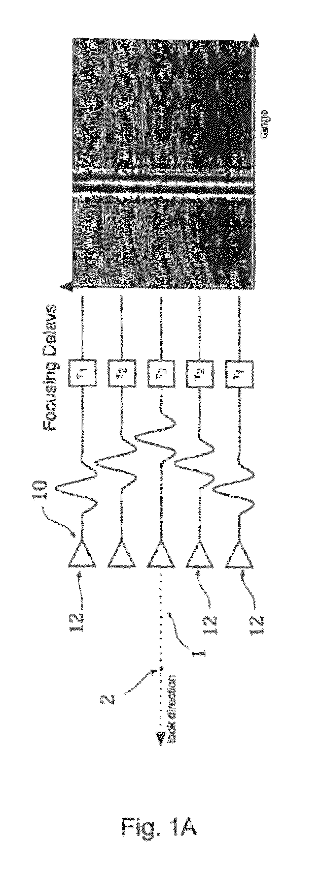
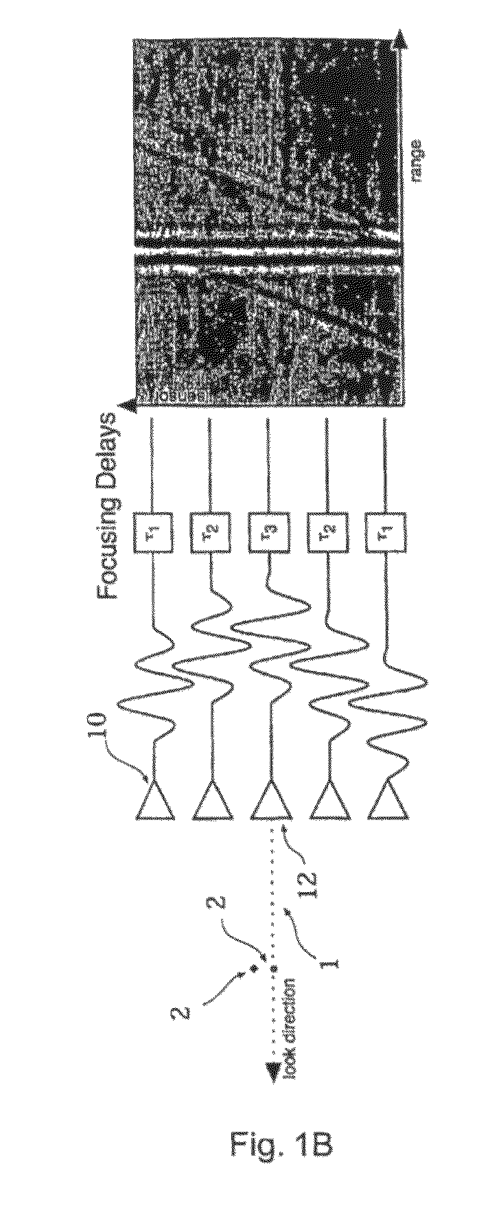
While this approach is straightforward and easy to implement, off-axis scatters, known as jammers in the RADAR / SONAR literature, can introduce clutter, reducing the overall quality of the beamformer output.
It is often the case that limited data are available, making computation of a reliable covariance matrix difficult.
In medical ultrasound, bright off-axis targets can seriously degrade image quality by introducing broad image clutter, which reduces image contrast and resolution.
The unique characteristics of ultrasound data make blind application of existing adaptive beamforming algorithms unlikely to be successful.
Although initial results are positive, the use of synthetic transmit poses significant limits on the application of these algorithms in real clinical environments because of potential motion artifacts and limitations of existing hardware.
Most adaptive beamforming algorithms, such as those previously described, tend to fail when applied to medical ultrasound data.
Failure can be attributed to one or more of the following factors: the medical ultrasound data is procured in a near-field scenario; the signals obtained that make up the medical ultrasound data are broadband; and there is limited statistical information available, as noted.

Method used


Image

  • Systems and method for adaptive beamforming for image reconstruction and/or target/source localization
  • Systems and method for adaptive beamforming for image reconstruction and/or target/source localization
  • Systems and method for adaptive beamforming for image reconstruction and/or target/source localization

Examples


example 1

Beamplots

[0164]A series of adaptive algorithms (Frost, Duvall, SSB, and an adaptive algorithm according to an embodiment of the present invention) were compared directly to the conventional delay-and-sum beamforming. Beamplots were generated for a 32 and a 64 element array. The array was operating at 5 MHz with roughly 70% fractional bandwidth. For calculation of the array manifold matrix 66, hypothetical sources were placed every 20 μm in range and every 100 μm in azimuth for the 32 elements array, shown in FIG. 7, and every 150 μm in azimuth for the 64 element case, shown in FIG. 8. In this and the following simulations, data was first demodulated to obtain IQ signals from which processing according to the present invention was performed.

example 2

Point Targets

[0165]A series of point targets were distributed within a 4×5 mm region in range and azimuth, respectively. A 33 element linear array operating at 5 MHz with element spacing of 150 μm was simulated. The final sampling frequency was set at 40 MHz. A plane wave was used on transmit for both the conventional beamforming and the processing according to the present invention. Conventional beamforming was applied on the received RF data using Hann apodization and dynamic receive focusing. Apodization is a signal processing technique used in medical ultrasound to generate images with lower side-lobe level at the price of coarser main-lobe resolution. For the processing according to an embodiment of the present invention, the image region was discretized into a series of hypothetical targets separated 20 μm in range and 120 μm in azimuth. The positions of the hypothetical sources were chosen so that some, but not all coincided with the positions of the actual point targets. The...

example 3

Wire Targets

[0166]5 wires (20 μm in diameter) in a water bath. FIG. 10A shows the output of a Philips SONOS 5500 ultrasound imaging system. FIG. 10B shows the image of the five wires as reconstructed by the present invention. Hypothetical sources were placed every 20 microns axially (range) and every 67 microns laterally (azimuth).


PUM


Abstract

Methods, systems and computer readable media for reconstruction of target locations and amplitudes from signals received from one or more real targets in a space are provided, wherein the signals are at least one of signals received from the near-field and broadband signals. The space is modeled as a region of interest, and an array manifold matrix is calculated from signals received from hypothetical targets in the region of interest. One or more signal vectors received from the one or more real targets are reshaped into a data vector. A hypothetical target configuration is identified that, when applied to a signal model comprising the array manifold matrix, matches the data vector, a reconstruction vector is calculated. The reconstruction vector is reshaped into a reconstructed representation of the real targets in the space, and at least one of outputting the reconstructed representation for viewing by a user, and storing the reconstructed representation for later use are performed.

Description

[0001]This invention was made with government support under federal Grant No. W81XWH-04-1-0590 awarded by the U.S. Army Congressionally Directed Medical Research Program. The United States Government has certain rights in this invention.[0002]This application claims priority to U.S. Provisional Application No. 60 / 718,290 filed Sep. 19, 2005, entitled “Method and System for Adaptive Beamforming for Medical Ultrasound Imaging”, which is hereby incorporated by reference herein in its entirety.FIELD OF THE INVENTION[0003]The present invention relates to imaging devices and techniques. More specifically, the various embodiments of the present invention provide a novel image formation system and method that allows for near field and / or time domain imaging and localization applications.BACKGROUND OF THE INVENTION[0004]Sensor arrays are used in many application fields including RADAR, SONAR, geophysics, telecommunications and medical imaging. For these applications, the received data is oft...

Claims


Application Information

Patent Timeline
Patent Type & Authority Patents(United States)
IPC IPC(8): G06K9/00H04W8/02
CPCG01S7/52046G01S7/52026G01S7/5205G01S7/52052G01S15/8977
Inventor WALKER, WILLIAM F.VIOLA, FRANCESCO
Owner UNIV OF VIRGINIA ALUMNI PATENTS FOUND
Why Eureka
Try Eureka