Structure of front section of vehicle body

a front section and body technology, applied in the direction of bumpers, roofs, vehicular safety arrangments, etc., can solve the problems of reduced connecting rigidity, reduced handling stability and torsional rigidity of the vehicle body, etc., to achieve the effect of ensuring the connection strength of the connected section between the front side frames and the front bulk head, reducing the risk of collision, and reducing the impact for

Active Publication Date: 2014-07-01
HONDA MOTOR CO LTD
View PDF14 Cites 16 Cited by
  • Summary
  • Abstract
  • Description
  • Claims
  • Application Information

AI Technical Summary

Benefits of technology

[0017]In the invention, as defined in claim 1, the longitudinal length of the engine compartment is shortened to create a short overhang, and the impact-absorbing members can be of sufficient longitudinal length. In other words, the areas (longitudinal lengths) where light collisions are counteracted by the impact-absorbing members can be enlarged to the maximum limit. Furthermore, the connection strength of the connected section between the front side frames and the front bulk head can be sufficiently ensured.
[0018]In the invention, as defined in claim 2, because the front end parts of the front side frames are provided with the impact-absorbing members extending farther forward than the front bulk head, the impact-absorbing members can be extended forward past the front bulk head. As a result, the input of light collision loads to the front bulk head can be slowed.
[0019]In the invention, as defined in claim 3, because the side stays have closed cross section shapes and the front end parts of the front side frames comprise flanges extending laterally inward and overlapping the closed cross sections of the side stays in the longitudinal and lateral directions of the vehicle body, the connecting rigidity between the side stays and the front side frames can be further increased, and the efficiency of load transference from the front bulk head to the front side frames during front collisions can be improved.
[0020]Furthermore, spot welds for connecting the front side frames and the front bulk head can be ensured by flanges. It is thereby possible to avoid narrowing the cross sections of the front side frames in order to ensure spot welds. As a result, the cross sections of the front side frames can be enlarged.
[0021]In the invention, as defined in claim 4, because the front end parts of the front side frames and the front end parts of the upper frames are connected together so that the front end surfaces thereof are coplanar and the horizontally long attachment sections extending laterally are formed on the front end surfaces, the connected sections and the front end parts of the upper frames can cooperate to further increase the connecting rigidity of the connected sections.
[0022]In the invention, as defined in claim 5, because the impact-absorbing members are disposed on the horizontally long attachment sections so as to laterally overlap the front end parts of the upper frames, the lateral areas of the impact-absorbing members can be enlarged, and light collision performance can be improved. Furthermore, because front collision loads are inputted more rapidly to the upper frames, the efficiency of load transference can be improved and loads inputted to the connected sections can be reduced.

Problems solved by technology

This connected section is a connected section between front and rear members (front side frames) and left and right members (the front bulk head) forming the engine compartment, and the vehicle body may lose handling stability and torsional rigidity due to a decrease in the connecting rigidity.

Method used


Image

  • Structure of front section of vehicle body
  • Structure of front section of vehicle body
  • Structure of front section of vehicle body

Examples


embodiment 1

[0033][Embodiment 1]

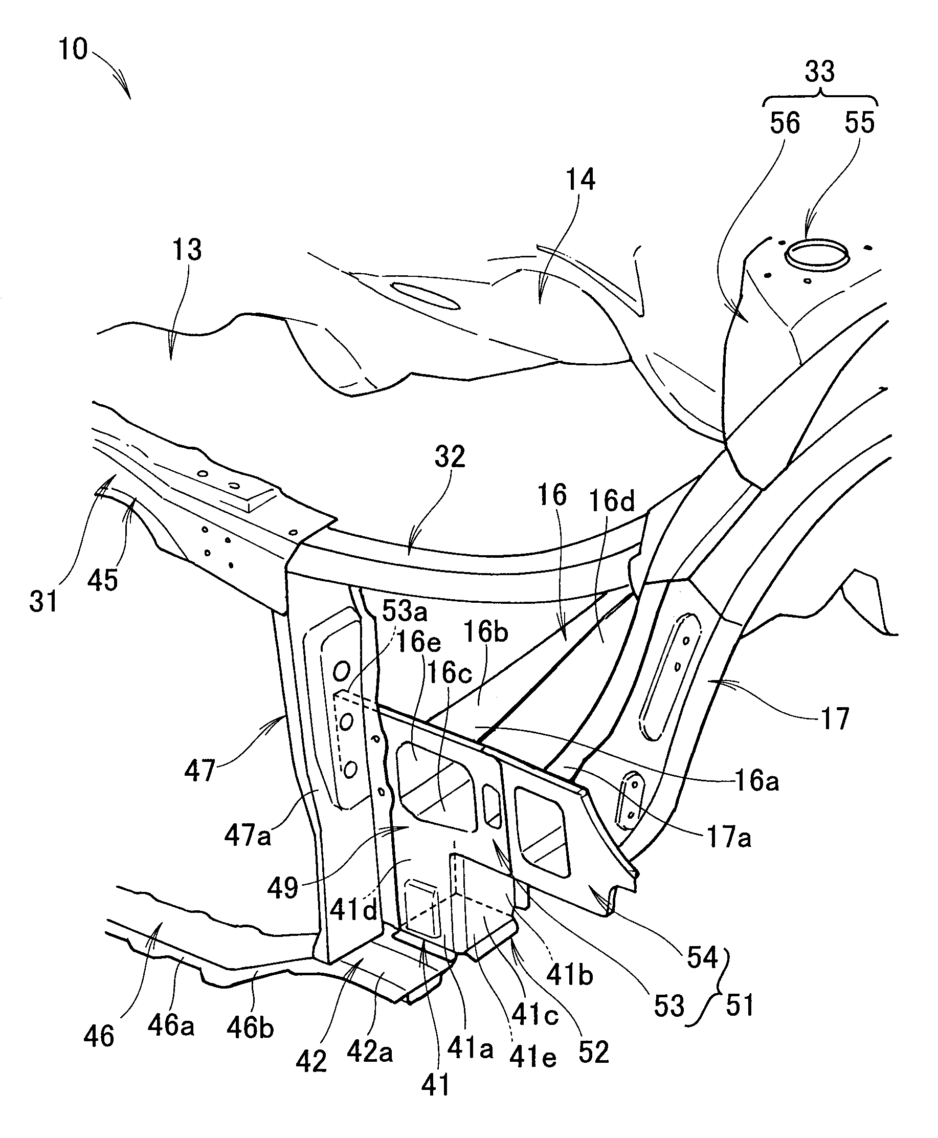
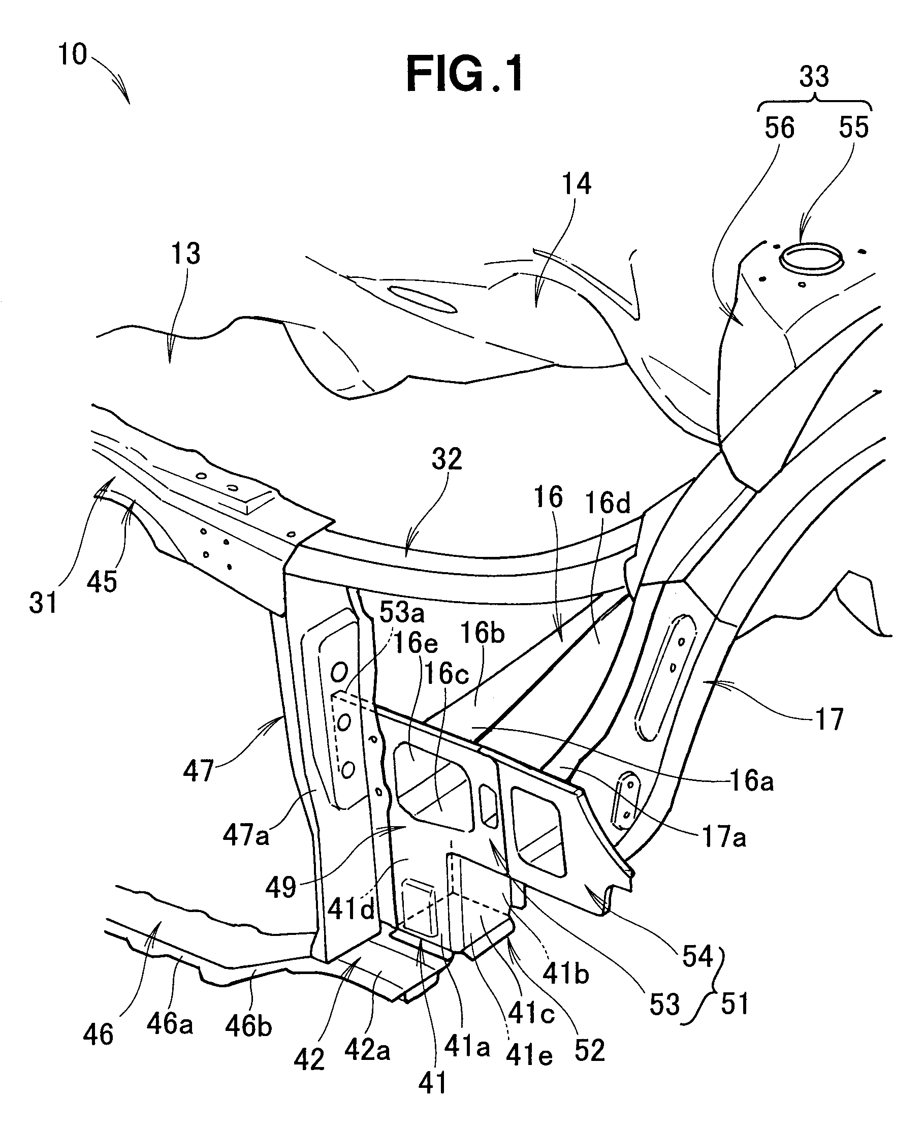
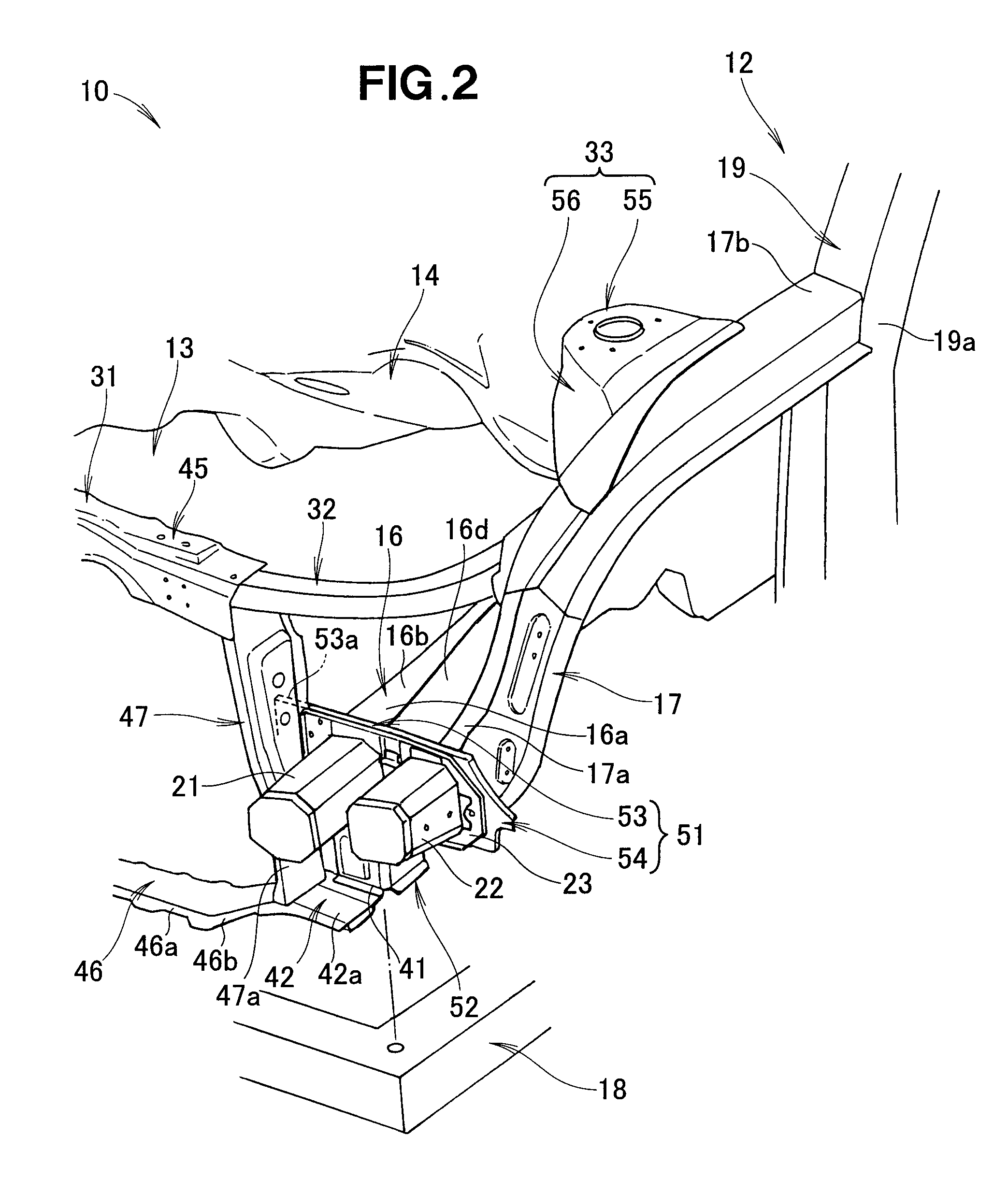
[0034]A vehicle front body structure 10 includes a front bulk head 31 formed into a rectangular shape as viewed from the front, as shown in FIGS. 1 through 5. A front side frame 16 extends longitudinally in the vehicle body at the laterally outer side of the front bulk head 31. A front sub frame 18 is supported on the bottom part of the front side frame 16, and an engine (not shown) and a gear box (not shown) are installed thereon.

[0035]An upper frame (upper member) 17 is aligned with the front side frame 16 on the outer side, and is curved upward toward the rear of the vehicle body. A rear end section 17b of the upper frame 17 is connected to a front pillar 19 forming the framework of the side front section of a passenger compartment (cabin) 12. A dashboard 14 partitions an engine compartment 13 and the cabin 12. A damper section 33 supports a damper unit (not shown). The bottom part of the damper section 33 is connected to the front side frame 16.

[0036]An impac...

embodiment 2

[0068][Embodiment 2]

[0069]FIG. 6 shows the vehicle front body structure according to Embodiment 2. The same symbols are used to indicate the same components as the vehicle front body structure 10 according to Embodiment 1 shown in FIG. 3, and detailed descriptions of these components are omitted. For the vehicle front body structure according to Embodiment 2, an example is presented in which one impact-absorbing member 61, wide in the lateral direction, is used instead of the two extensions of the inner inner-side impact-absorbing member 21 and the outer outer-side impact-absorbing member 22 of the vehicle front body structure of Embodiment 1.

[0070]In the vehicle front body structure 60 according to Embodiment 2, the impact-absorbing member 61 extending farther forward than the front bulk head 31 is provided to the front end part 16a of the front side frame 16, and the impact-absorbing member can therefore be extended forward past the front bulk head 31. As a result, input of light ...


PUM


Abstract

A structure of the front section of a vehicle body is disposed on the front end portion of a front side frame on the same position as the rear surface of a side stay in the front-rear direction of the vehicle body, and includes a first extending portion extending downward along the rear surface of the side stay. A lower stay is provided with a second extending portion extending outward in the vehicle width direction beyond the side stay to a position below the first extending portion. A joining section is formed so as to join the front surface of the first extending portion, the upper surface of the second extending portion, and outside surface of the side stay. The joining section defines an arrangement region for inner and outer shock absorbing members having a lower rigidity than the front side frame.

Description

TECHNICAL FIELD[0001]The present invention relates to a vehicle front body structure which includes: left and right front side frames extending longitudinally of a vehicle body in laterally outer areas of a front bulk head of rectangular shape as viewed from a front side; and an impact-absorbing member provided to the front end of the front side frames.BACKGROUND ART[0002]The thus-arranged vehicle front body structure is known as is disclosed in Patent Document 1, for example.[0003]The vehicle front body structure disclosed in Patent Document 1 comprises left and right front side frames extending longitudinally in the vehicle body at the left and right sides of the vehicle body, a bumper beam extending laterally in front of the front side frames, an impact-absorbing member (a crash pipe) connected to the left and right ends of the bumper beam and extending rearward in the vehicle body, the rear end being fastened to the front ends of the front side frames, and a front bulk head (a s...

Claims


Application Information

Patent Timeline
Patent Type & Authority Patents(United States)
IPC IPC(8): B60R19/34B62D25/08B62D21/15
CPCB62D25/085B62D25/084B62D25/08B62D21/152B60R19/34B62D25/082
Inventor KIHARA, MAKOTOICHIKAWA, SHUJITAKEDA, TOMOYA
Owner HONDA MOTOR CO LTD
Why Eureka
Try Eureka