Wind turbine blade

a technology of wind turbine blades and blades, which is applied in the direction of liquid fuel engines, vessel construction, marine propulsion, etc., can solve the problem that neither of the spar segments has the protruding spar caps, and achieve the effect of increasing the reliability of the connection and high laminate quality

Active Publication Date: 2014-07-01
BLADE DYNAMICS LTD
View PDF20 Cites 24 Cited by
  • Summary
  • Abstract
  • Description
  • Claims
  • Application Information

AI Technical Summary

Benefits of technology

[0018]In particular, neither of the spar segments has the protruding spar caps which are susceptible to damage during transportation. Secondly, the two spar segments or the two spar caps can be precisely aligned with respect to one another in their final position before the connection piece is fitted. This simplifies the assembly process and reliability of the joint. The connection piece is a small component which is easy to handle. It is brought into place in a direction which is close to being orthogonal to the direction in which the tapered surfaces extend. Therefore, any scraping between adjacent tapered surfaces caused by slight misalignment of the components is far less likely to occur. Even if it does occur, the orientation of the surfaces means that touching which does occur will have a significantly reduced effect. This greatly increases the reliability of the bond.
[0031]This provides a method which is extremely versatile, and yet relies on a relatively small number of component parts and assembly jigs. The spar caps have the same external shape and size in order to be assembled in the same U-shape channel. This may (if required) be the channel in which the spar caps are initially formed, thereby further reducing the required tooling. However, the process remains versatile in that the depth of the web can be varied to create beams of different heights, and even to create beams with heights that vary along their length. Also, by offsetting the first and second spar beam when they are joined side by side, a virtual “twist” can be incorporated into the beam. Thus, from a very small set of component parts and very simple tooling, complex beam shapes can be produced.

Problems solved by technology

In particular, neither of the spar segments has the protruding spar caps which are susceptible to damage during transportation.

Method used


Image

  • Wind turbine blade
  • Wind turbine blade
  • Wind turbine blade

Examples


Embodiment Construction

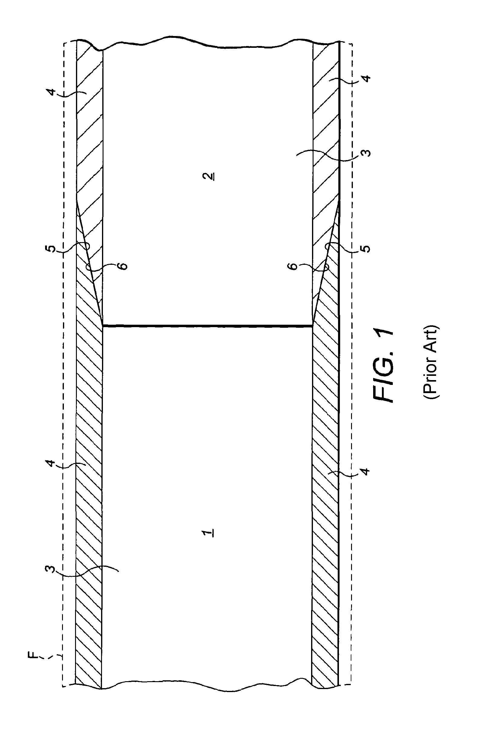
[0044]The spar comprises two spar segments 7 which are essentially the same in structure as the second spar segment 2 shown in FIG. 1. Each has a shear web 3, made of the multi-axial material and spar caps 4 are provided on either side which are formed predominantly of a uni-axial material which are preferably formed as pulltrusions, but could also be made from prepreg, laminations or other pre-forms known in the art which give cost effective spar caps with good mechanical properties.

[0045]Further details of the construction and materials of the spar sections are disclosed in our own earlier WO 2009 / 034291.

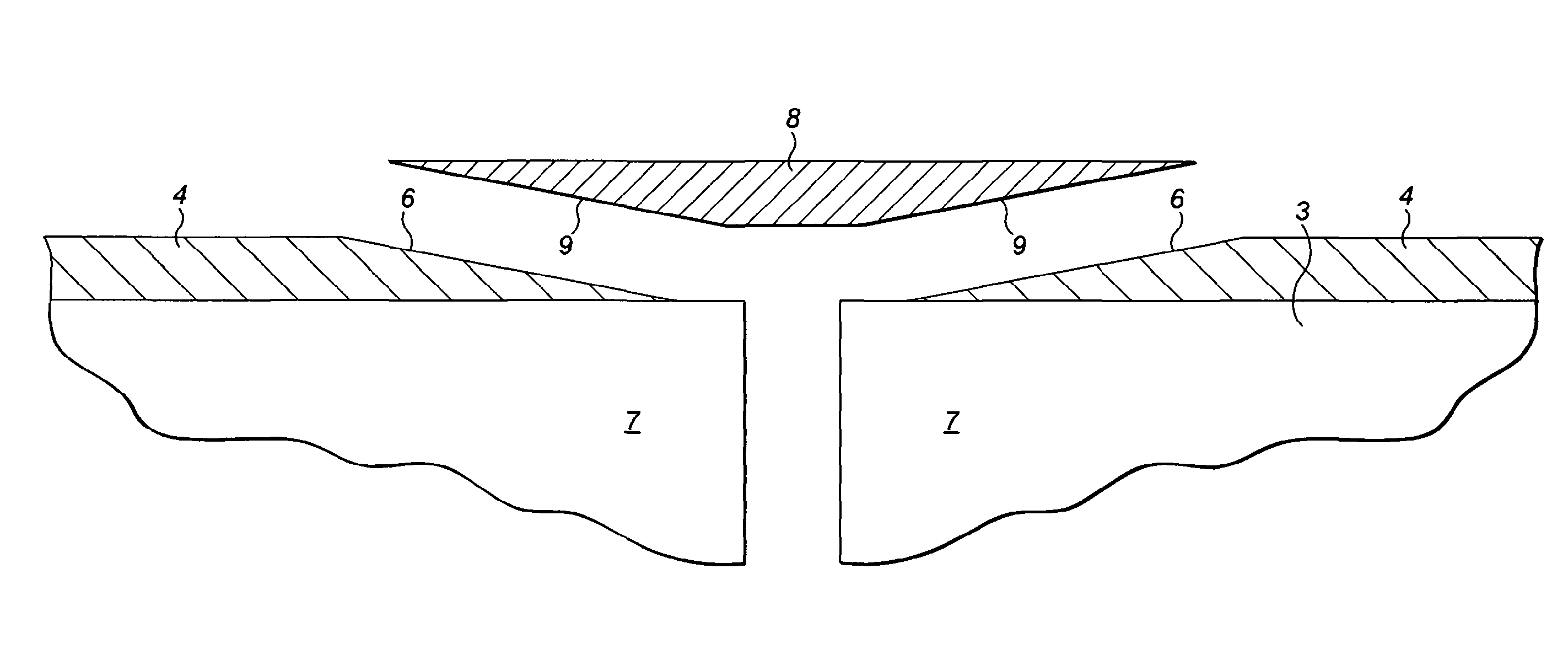
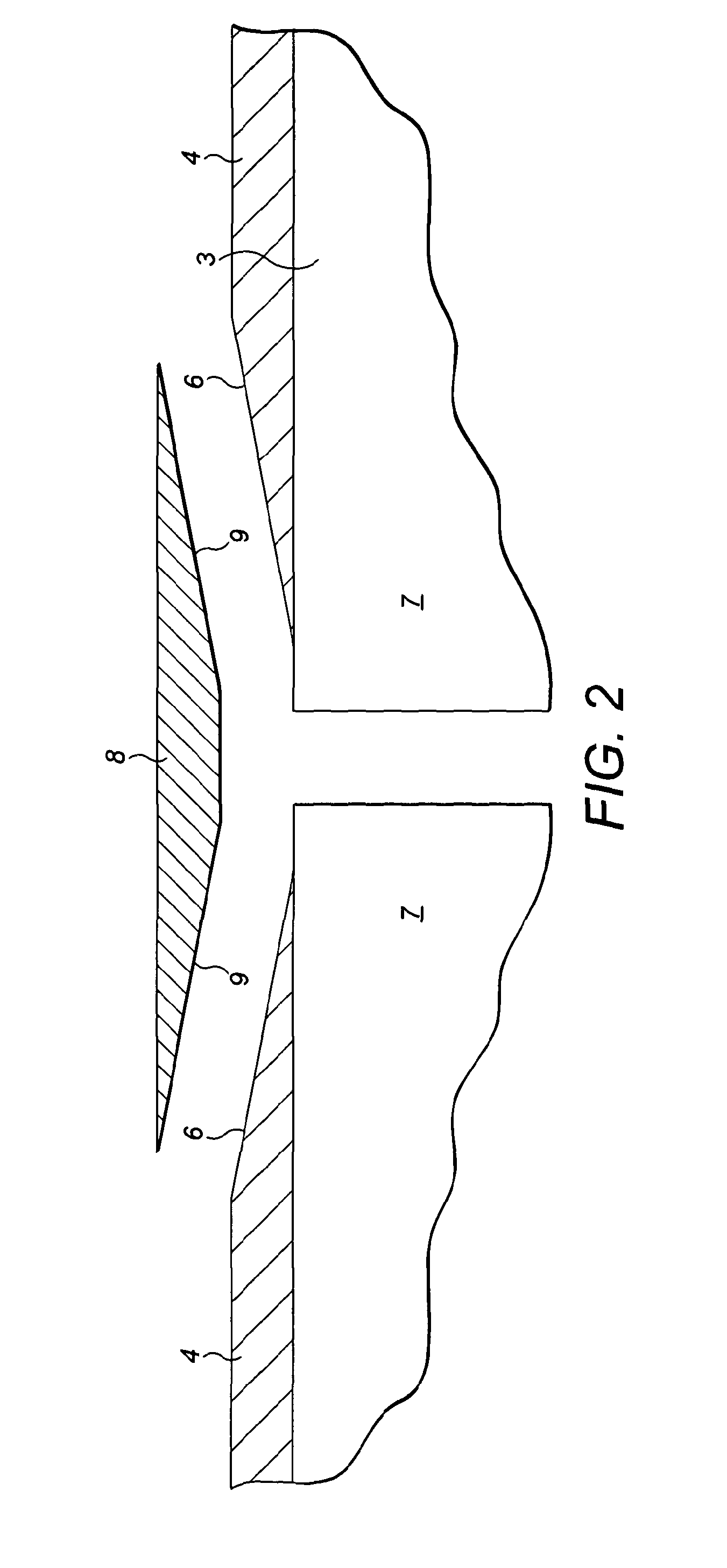
[0046]At the end adjacent to the joint, each of the spar caps 4 has a tapered surface 6 as described above in relation to FIG. 1.

[0047]A pair of connection pieces 8 have a width and depth which corresponds to the width and depth of the adjacent spar caps 4 and have inclined faces 9 which correspond to the inclined faces 6 of the spar caps 6 so that, in use, as shown in FIG. 3, the...


PUM

PropertyMeasurementUnit
temperatureaaaaaaaaaa
axial lengthaaaaaaaaaa
depthaaaaaaaaaa

Abstract

A wind turbine blade comprising an aerodynamic fairing supported along at least a portion of its axial length by a spar (12). The spar comprises at least two spar segments (12) joined end-to-end at an interface (9), each spar segment comprising a shear web (3) with a spar cap (4) on each side. The outer face (6) of each spar cap tapers inwardly towards the interface such that its depth is reduced towards the interface creating a recess on each side of the interface formed by the tapered faces of adjacent spar caps. A respective connection piece (8) is sized to fit into each recess. Each connection piece (8) is sized to fit into each recess. Each connection piece (8) being fixed to the tapered faces of adjacent spar caps to form a double scarf joint.

Description

CROSS-REFERENCE TO RELATED APPLICATIONS[0001]This application is a continuation of Patent Cooperation Treaty International Patent Application PCT / GB2011 / 001035, filed Jul. 8, 2011, and entitled “A WIND TURBINE BLADE,” which is incorporated by reference herein in its entirety, and which claims priority to Great Britain Patent Application 1011539.2, filed on Jul. 8, 2010.BACKGROUND OF THE INVENTION[0002]1. Field of the Invention[0003]The present invention relates to a wind turbine blade.[0004]2. Description of the Related Art[0005]There is an increasing trend for longer and longer wind turbine blades. This has led to a recent development whereby each blade is manufactured in a number of sections which are connected end-to-end in order to form the finished blade. The joint between these adjacent sections is critical to the operation of the blade.[0006]Such wind turbine blades generally comprise an aerodynamic fairing supported by a longitudinally extending spar. In any blade consisting...

Claims


Application Information

Patent Timeline
Patent Type & Authority Patents(United States)
IPC IPC(8): F03D1/06
CPCF03D1/0633F05B2240/302Y02E10/721F03D1/0675Y10T29/49339B29C70/40B29C70/84Y02E10/72
Inventor HAYDEN, PAUL TREVORBEHMER, HARALD
Owner BLADE DYNAMICS LTD
Why Eureka
Try Eureka