
Multi-core, multi-blade, and multi-node network environment simulation

a network environment and simulation technology, applied in the field of network work, can solve the problems of not being able to fully simulate a fiber network, unable to fully test a complex embedded software system, and the hardware that the software is supposed to run on is usually not availabl

Active Publication Date: 2014-07-08
CIENA
View PDF3 Cites 6 Cited by
  • Summary
  • Abstract
  • Description
  • Claims
  • Application Information

AI Technical Summary

Problems solved by technology

With respect to development and testing of software related to a particular network element, hardware that the software is supposed to run on is usually not available due to expense, limited availability of the hardware, or simply that the hardware has not been designed and prototyped yet.
Conventionally, there does not exist a fully encompassing simulation of a fiber network that allows the developers to fully test a complex, real time, embedded software system down to the driver level.

Method used


Image

  • Multi-core, multi-blade, and multi-node network environment simulation
  • Multi-core, multi-blade, and multi-node network environment simulation
  • Multi-core, multi-blade, and multi-node network environment simulation

Examples


Embodiment Construction

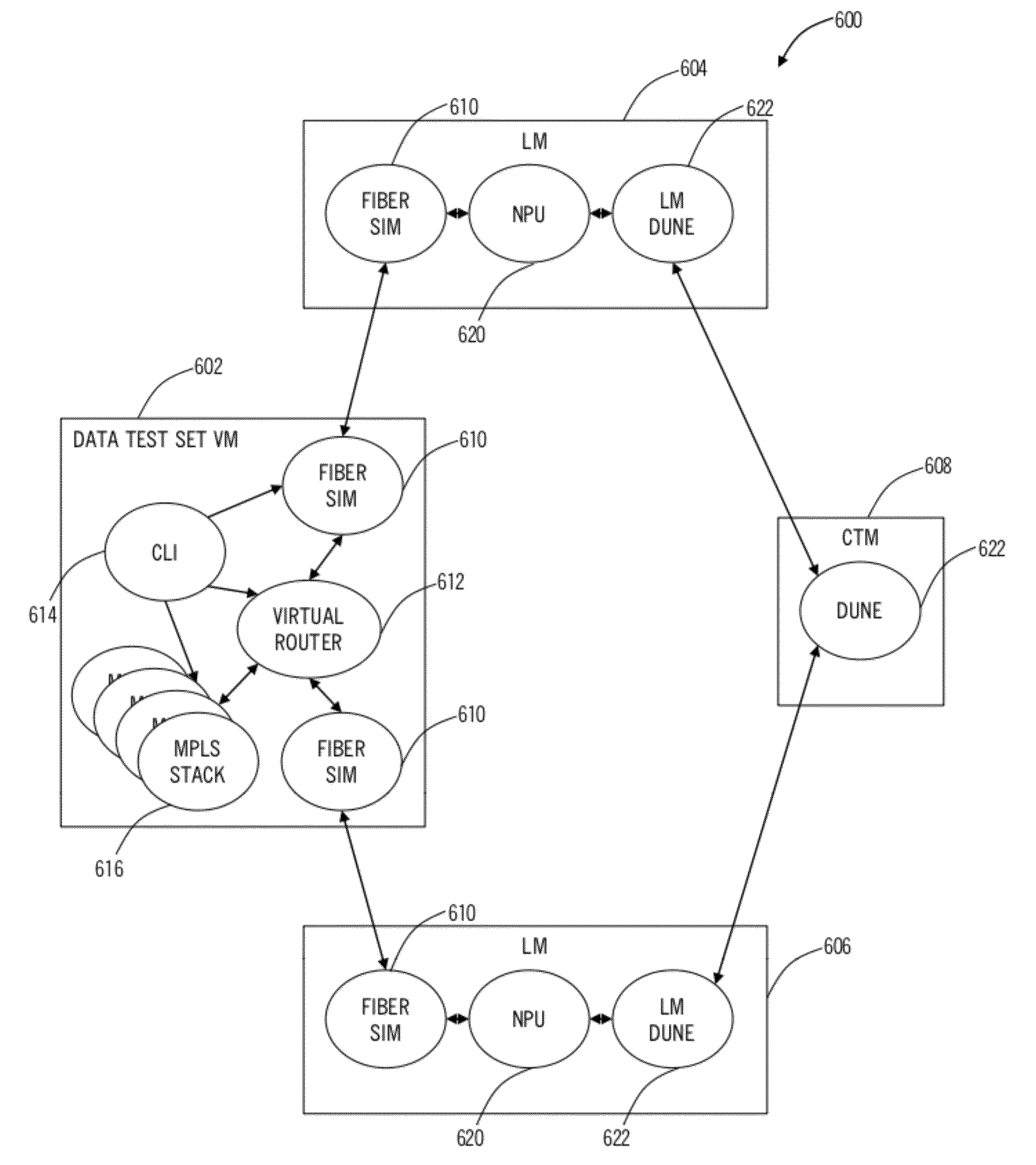
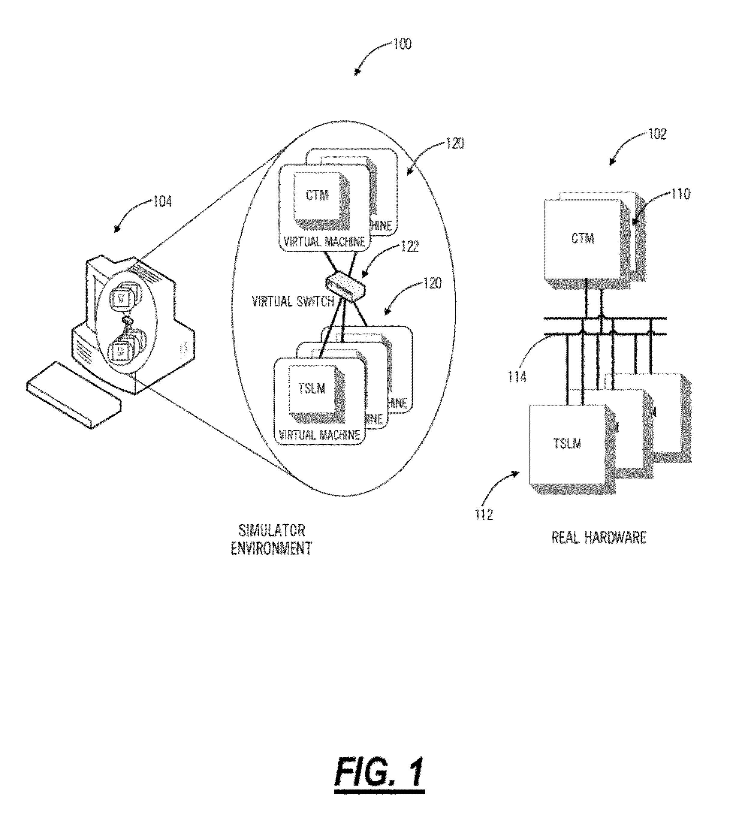
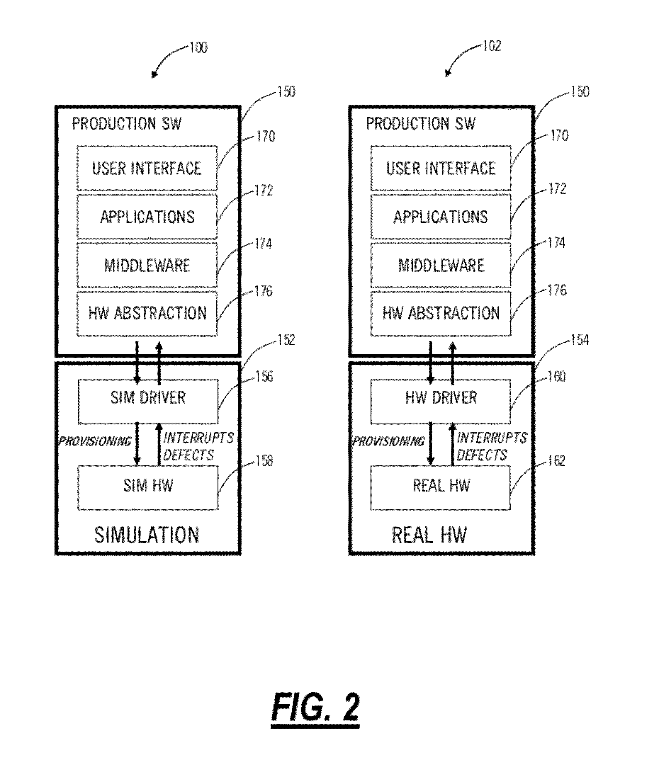
[0015]In various exemplary embodiments, the present invention provides systems and methods for a simulation environment that simulates hardware at a fiber level, a data plane level, a card level, and a chassis level. The simulation environment may be utilized in development and testing of complex, real time, embedded software systems, such as, for example, routers, switches, access devices, base stations, optical switches, optical add / drop multiplexers, DWDM devices, Ethernet switches, Optical Transport Network (OTN) switches, and the like. In an exemplary embodiment, the simulation environment operates on one or more workstations utilizing a virtual machine to operate a virtualized module, line card, line blade, etc. Further, a plurality of virtual machines may operate together to operate a virtualized chassis forming a network element. Advantageously, the present invention provides state of the art data plane traffic and control plane simulation that reduces development time and c...


PUM


Abstract

The present disclosure provides systems and methods for a simulation environment that simulates hardware at a fiber level, a data plane level, a card level, and a chassis level. The simulation environment may be utilized in development and testing of complex, real time, embedded software systems, such as, for example, routers, switches, access devices, base stations, optical switches, optical add / drop multiplexers, Ethernet switches, and the like. In an exemplary embodiment, the simulation environment operates on one or more workstations utilizing a virtual machine to operate a virtualized module, line card, line blade, etc. Further, a plurality of virtual machines may operate together to operate a virtualized chassis forming a network element and with a plurality of virtualized chassis forming a network. Advantageously, the present invention provides state of the art data plane traffic and control plane simulation that reduces development time and cost while increasing design flexibility.

Description

FIELD OF THE INVENTION[0001]The present invention relates generally to networking. More particularly, the present invention relates to a network simulation system and method providing a simulation environment for the development and testing of complex, real time, embedded software systems.BACKGROUND OF THE INVENTION[0002]Conventional networks typically include interconnected network elements or nodes in various configurations. Example network elements may include routers, switches, access devices, base stations, optical switches, optical add / drop multiplexers, dense wave division multiplexers (DWDM), and the like. Each network element includes a combination of hardware, software, and firmware and typically a physical implementation includes a plurality of modules, cards, blades, etc. interconnected via an interface such as a backplane, mid-plane, etc. Effectively, each network element is a complex, real time, embedded software system. With respect to development and testing of softw...

Claims


Application Information

Patent Timeline
Patent Type & Authority Patents(United States)
IPC IPC(8): G06F9/44G06F9/455G06F9/48G06F9/50G06F11/30G06F13/10G06F13/12G06F21/53
CPCG06F9/45504G06F9/45533G06F9/4856G06F9/5077G06F11/301G06F21/53G06F2009/4557G06F2009/45595G06F2212/151H04L41/145
Inventor CARROLL, JONDIMOLA, DOUGFREZELL, ANDREW
Owner CIENA
Learn More