
Technique for management of communication networks

a communication network and communication technology, applied in the field of communication network management technology, can solve the problems of affecting traffic, affecting the operation of the network, and unable to see at a glance the whole picture of the communication, so as to achieve the effect of effective (accurate and inexpensive) method and system for managing/controlling the operation of the communication network

Active Publication Date: 2014-07-08
ECE TELECOM LTD
View PDF6 Cites 2 Cited by
  • Summary
  • Abstract
  • Description
  • Claims
  • Application Information

AI Technical Summary

Benefits of technology

The present invention introduces a technology for managing communication networks by a management system comprising at least two management layers. The invention allows for efficient and cost-effective management of networks, minimizing traffic disruption and improving network functioning. It is particularly useful for managing services comprising endpoints on different types of equipment. The invention enables changes in the network without affecting traffic in a negative manner.

Problems solved by technology

It is a well-known problem that, in present network management systems, a network operator cannot see at a glance the whole picture of a communication network to be managed especially while the network operator monitors or tries to introduce any changes in the network.
Such difficulty, of course, hampers both any reconfiguring of the network, and any attempts to change traffic flows in the network.
Since any changes cannot be adequately analyzed in advance at the upper level of network management it become traffic-affecting.
Different equipment samples have multiple, equipment-specific features and usually demonstrate significant technological gaps between them.
This means that their information bases and screens cannot be seen and / or used from other layers.
For example, if a user wishes to modify a multipoint-to-multipoint Ethernet service with multiple endpoints which are distributed over different pieces of equipment, there might be a situation when the service will be created successfully at part of the endpoints, while at other endpoints it will fail.
The failure may be caused by capabilities and features which may be supported / fulfilled by one type of equipment and not supported / fulfilled by other types of equipment.
Such a situation is very undesirable for the end user since the service will appear to be only partially functional.
Today there is no suitable pro-active approach which would allow the users to prevent such situation in a complex network comprising heterogeneous equipment.
In other words, a modern network management system (NMS) is unable “to see” the whole picture of the network, with its complete set of its capabilities and features.
Another example of a problem with the prior art, is that Services Definition and a current specific Quality of Service (QoS) model for traffic can usually be seen / managed only at the layer of EMS (e.g., at its GUI).
This is a very difficult, cumbersome, time-consuming and error-prone process, especially nowadays when communication networks grow and their complexity increases.
On the other hand, full transfer of data from all EMSs to the NMS is also not practicable.
First of all, it would cause excessive development efforts at the stage of designing NMS.
Secondly, it would hamper the NMS operation, would make the working of EMSs cumbersome and would introduce a problem of synchronizing between EMSs and NMS.
An additional problem existing today is that the operator has no comprehensive tools to analyze the network and perform “if-then” (AKA “what-if”) simulations for various scenarios of hardware and / or traffic reconfigurations in the network.
Such planning tools are isolated, self-contained applications.
Thus, the resulting solution found by such a planning tool may suffer from: low accuracy, and poor feasibility.
In addition other problems may arise from the very limited information which is available to the specific planning tool with respect to other, lower management layers of the system.
However, the above patent refers only to the optical technological layer, and only to a very limited set of changes which could be simulated For example the substitution of one entity (e.g. a network element or optical channel) to another is made.

Method used


Image

  • Technique for management of communication networks
  • Technique for management of communication networks
  • Technique for management of communication networks

Examples


Embodiment Construction

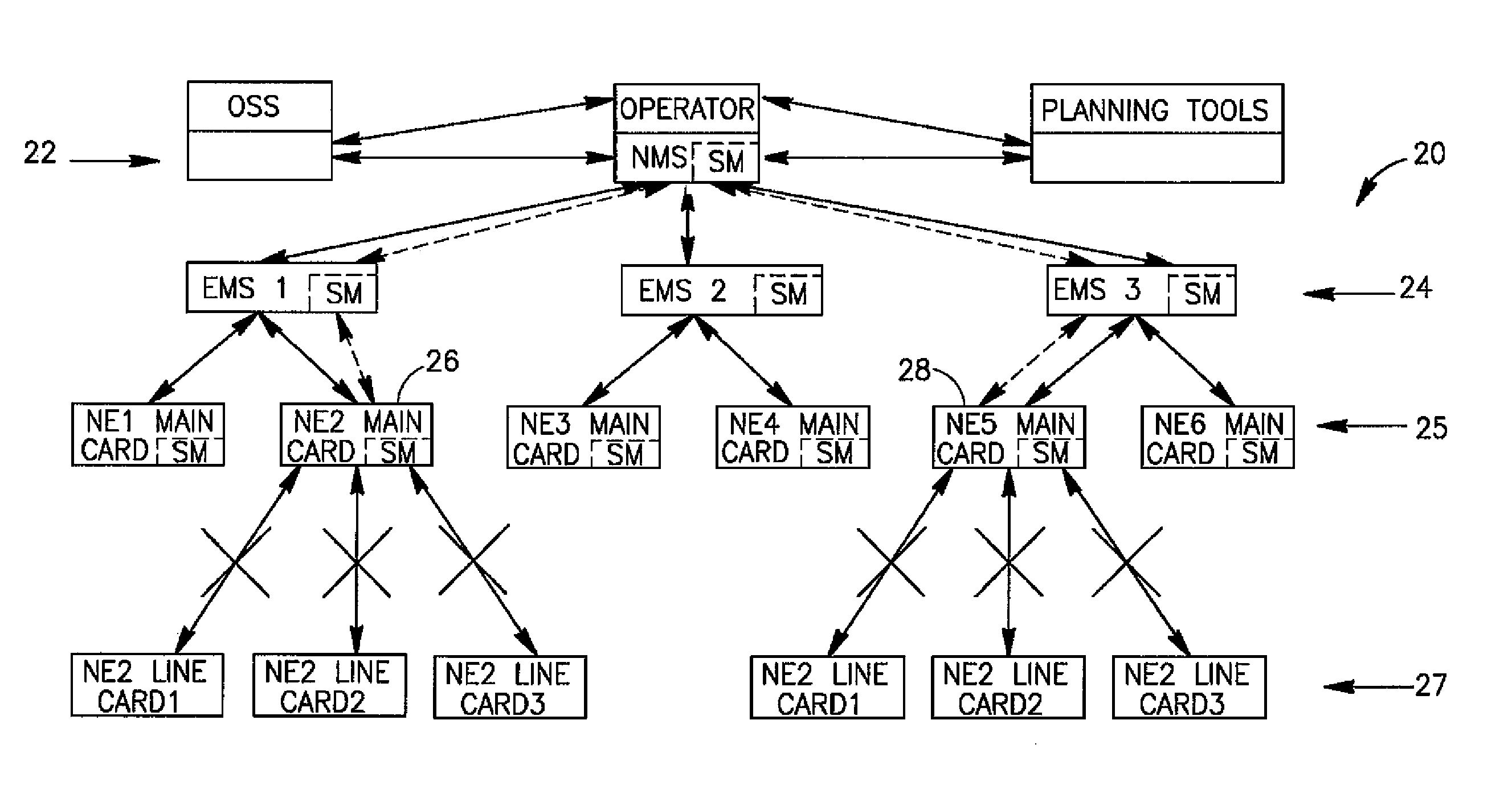
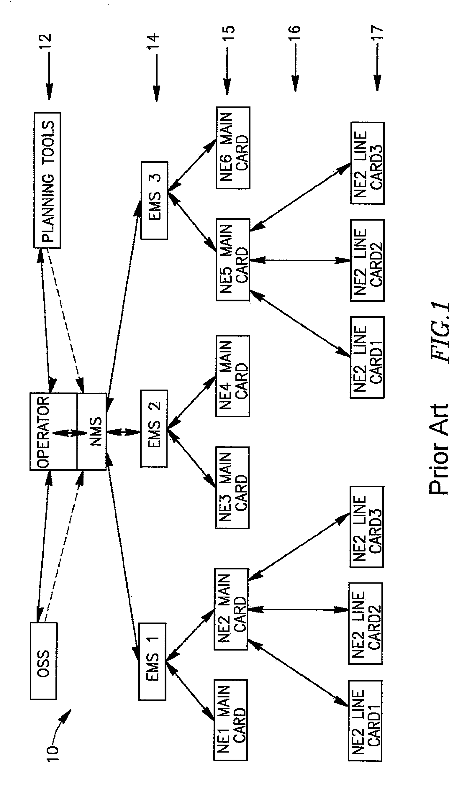
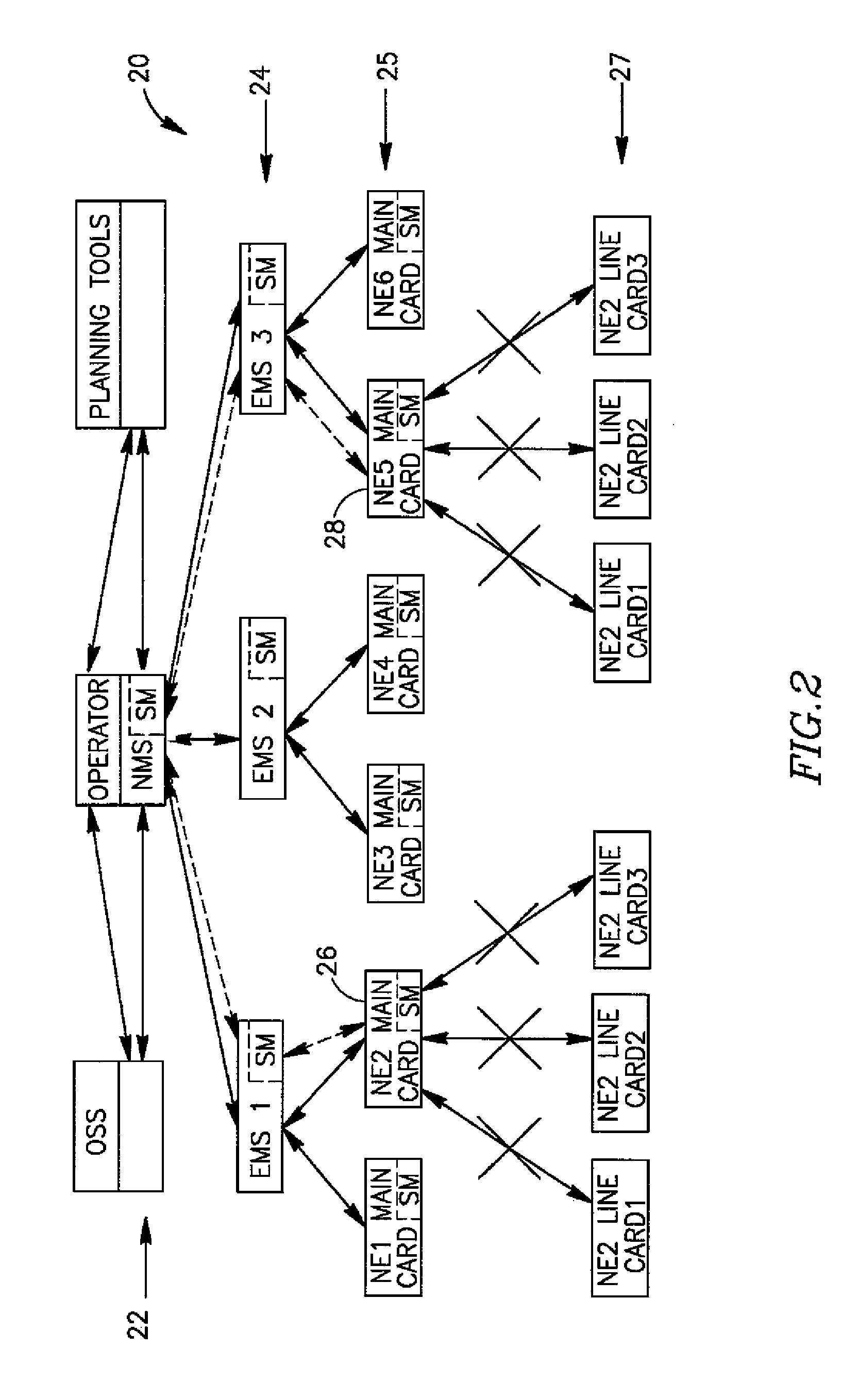
[0065]FIG. 1 illustrates a generalized block diagram of an exemplary multi-layer management system 10 in the prior art. The upper layer of management 12 is supervised by an Operator and comprises the NMS block and two optional blocks (Operation Support System OSS and planning tools) which are in communication with the NMS. The planning tools block may be considered to belong either to the management layer of NMS, or to be the uppermost layer of management. An EMS management layer 14 is an intermediate layer, which comprises EMS devices / software in communication with the NMS. Each EMS manages a number of Network Elements NE.

[0066]Each of the NEs is usually a complex switching equipment piece. NEs may be routers, switches, cross-connectors, DSLAMs, or the like manufactured by various companies and connected to a number of clients. The plurality of NEs 16 form an NE management layer 15 (which is an NE main cards sub-layer) and an NE line card sub-layer 17 (which is a basic layer of the...


PUM


Abstract

A method of managing a communication network, using a multi-layer management system having at least two management layers each comprising one or more elements, which elements serving as managing entities and / or managed objects. The method comprises performing a network operation simulation at a selected management level of the system, by one or more selected managing entities, while, at the time of the simulation, comprises interrupting management communication between the one or more selected managing entities and elements in an underlying management layer.

Description

CROSS-REFERENCE TO RELATED APPLICATIONS[0001]This application claims priority of Israel Patent Application No. IL 213159, filed May 26, 2011, the disclosure of which is incorporated by reference herein in its entirety.FIELD OF THE INVENTION[0002]The present invention relates to a technology of management of communication networks, and more specifically to a technology of introducing changes into a modern multilayer communication network by minimally affecting its traffic.BACKGROUND[0003]It is a well-known problem that, in present network management systems, a network operator cannot see at a glance the whole picture of a communication network to be managed especially while the network operator monitors or tries to introduce any changes in the network. Such difficulty, of course, hampers both any reconfiguring of the network, and any attempts to change traffic flows in the network. Since any changes cannot be adequately analyzed in advance at the upper level of network management it ...

Claims


Application Information

Patent Timeline
Patent Type & Authority Patents(United States)
IPC IPC(8): G06F15/173
CPCH04L12/413
Inventor DUKHOVNY, VADIM
Owner ECE TELECOM LTD
Learn More