Chopper for commingled fibers

a technology of commingled fibers and cutters, which is applied in the field of chopping fibers, can solve the problems of reducing productivity, dispensed fibers in an undesired orientation or position, and hard and abrasive glass fibers that wear rapidly and cannot be cut, so as to increase the efficiency of the cutting process

Active Publication Date: 2014-07-15
OWENS CORNING INTELLECTUAL CAPITAL LLC
View PDF11 Cites 9 Cited by
  • Summary
  • Abstract
  • Description
  • Claims
  • Application Information

AI Technical Summary

Benefits of technology

[0014]Guide plates are provided over the form adjacent the third and fourth feed screws. The guide plates are spring loaded. As a result of that spring loading the guide plates help guide the strand into the third and fourth feed screws and simultaneously bias the strand toward the first and second grinding wheels so as to increase the efficiency of the cutting process.

Problems solved by technology

The hard and abrasive glass fiber rapidly wears the rotating knives which dull and then cannot cut the thermoplastic fibers.
As a consequence, the knives must often be replaced thereby reducing productivity.
Chopped fibers are difficult to handle and on occasion one or more fiber segments are dislocated, potentially resulting in the fiber being dispensed in an undesired orientation or position.

Method used


Image

  • Chopper for commingled fibers
  • Chopper for commingled fibers
  • Chopper for commingled fibers

Examples


Embodiment Construction

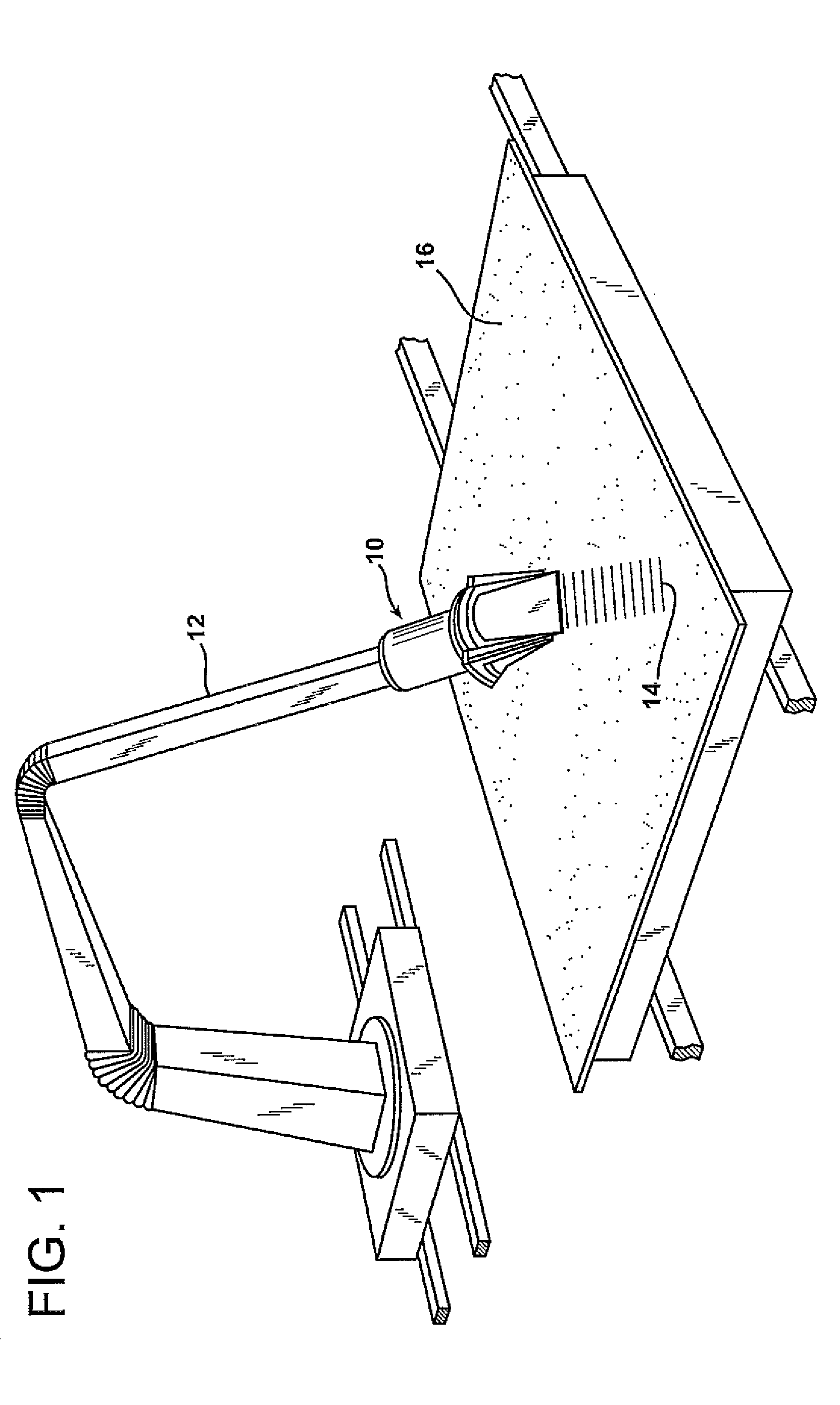
[0028]As illustrated in FIG. 1, a chopping device 10 is attached to a robot arm 12 that is positioned to deposit fiber segments 14 of a discrete / desired length onto a collection surface 16, such as a preform molding surface. Typically the collection surface is a screen. The chopping device 10 need not be robotized or automated and could even be stationary with the collection surface 16 being movable. A source of vacuum (not shown) is usually positioned beneath the screen to facilitate the preform making process. The robot arm 12 can be provided with a hydraulic system (not shown) or other similar system to enable the arm to be positioned adjacent or above a portion of the collection surface 16. The movement of the arm 12 can be controlled by computer (not shown) according to a predetermined pattern so that the desired pattern of fiber segments 14 is laid down on the collection surface 16.

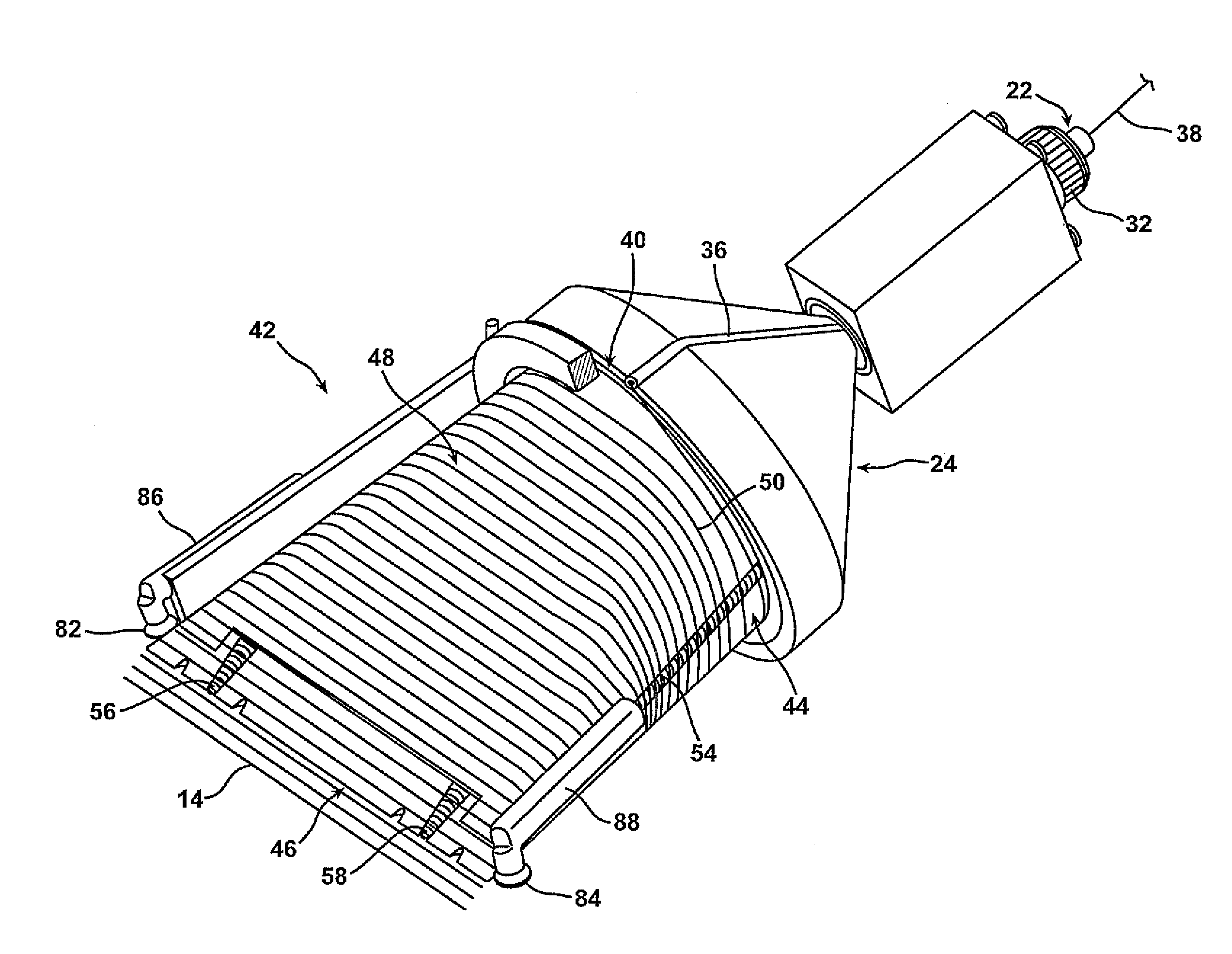
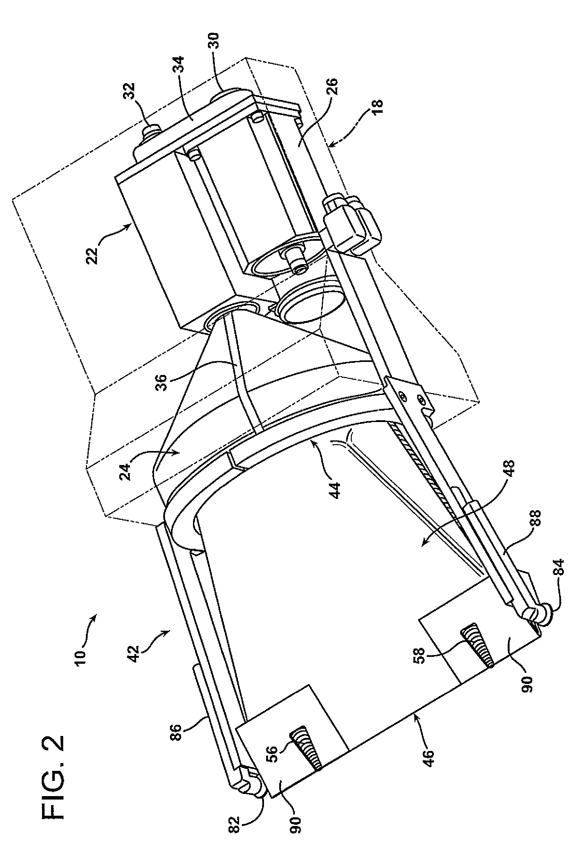
[0029]Reference is now made to FIGS. 2-4 illustrating the structure and operation of the choppin...


PUM

PropertyMeasurementUnit
diameteraaaaaaaaaa
diameteraaaaaaaaaa
speedaaaaaaaaaa

Abstract

A device for chopping fiber strand includes a form, and a strand feeding mechanism that delivers the strand to the form and conveys the strand along the form. First and second grinding wheels may be included to cut the strand into individual segments of desired length as the strand is conveyed along the form. A method of chopping a fiber strand includes the steps of delivering a continuous strand onto a base end of a form, conveying the continuous strand along the form from the base end toward a discharge end and cutting the continuous strand into individual segments of desired length, for example using first and second grinding wheels.

Description

RELATED APPLICATIONS[0001]This application is a national phase entry under 35 U.S.C. §371 and claims priority to International Application No. PCT / US2009 / 61569, with an International Filing Date of Oct. 22, 2009, for CHOPPER FOR COMMINGLED FIBERS, which claims the benefit of U.S. patent application Ser. No. 12 / 256,034 filed on Oct. 22, 2008, now abandoned, for CHOPPER FOR COMMINGLED FIBERS, the entire disclosures of which are fully incorporated herein by reference.TECHNICAL FIELD AND INDUSTRIAL APPLICABILITY OF THE INVENTION[0002]The present invention relates generally to the field of chopped fibers and, more particularly, to an apparatus and method for efficiently and effectively chopping a fiber strand into individual fiber segments of desired length which are then promptly dispersed in an orderly fashion.BACKGROUND OF THE INVENTION[0003]The process of cutting continuous reinforcement fibers into fiber segments of discrete length is useful in the manufacture of different types of ...

Claims


Application Information

Patent Timeline
Patent Type & Authority Patents(United States)
IPC IPC(8): B02C19/00
CPCB26D11/00D01G1/04B26D1/143B24B27/06Y10T83/6667
Inventor JANDER, MICHAEL, HORST
Owner OWENS CORNING INTELLECTUAL CAPITAL LLC
Why Eureka
Try Eureka