Tethered hovering platform

a technology of hovering platforms and rotors, which is applied in the direction of generators/motors, vertical landing/take-off aircraft, aircraft navigation control, etc., can solve the problems of expensive and complicated methods, instabilities of hovering platforms designed with ducted rotors or shrouded rotors, etc., and achieves simple design, simple use, and simple deployment

Active Publication Date: 2014-07-15
UNIVERSITY OF KANSAS
View PDF9 Cites 16 Cited by
  • Summary
  • Abstract
  • Description
  • Claims
  • Application Information

AI Technical Summary

Benefits of technology

[0032]The invention includes the use of tethers to enable a THP to operate in adverse atmospheric conditions using inherent stability to stay aloft. Hovering platforms designed with ducted rotors or shrouded rotors are plagued with instabilities. Traditionally these types of hovering vehicles are stabilized using expensive and complicated methods. The ideal UAV of today would be capable of all weather operation while still being inexpensive, relatively easy to use, and simple to deploy. An inexpensive concept would require low-cost parts and manufacturing processes as well as a simple design. Ease of use entails minimal human interaction as well as a simple interface. Simple deployment would require an easy integration of the concept into every possible application. These types of platforms can be used in various defense and security applications, and the use of tethers could enable a THP to operate in adverse atmospheric conditions using inherent stability to stay aloft. Some of these applications include border patrol, crowd control, counter narcotics, ordinance disposal, and search and rescue.
[0034]A small fixed rotor platform can have 3 tethers instead of 4. Consistent wobble type flight instability caused by the rotating momentum of the fixed propeller can be fixed by introducing system damping, which is an effective way to reduce the wobble instability to levels acceptable for the vehicle to perform the desired mission. Small lightweight passive dampers using a central constrained layer viscous-elastic polymer proved sufficient to provide the needed damping. The overall system design can be light weight and low cost. The weight of the sized components allowed for a platform that requires very small dampers and allows for the small inexpensive motors to provide sufficient thrust. The test platform successfully demonstrated stabilized flight in gusty conditions and also showed stable flight at a 20 ft height, although higher heights can be achieved. There is no known technology for a tethered platform that solves the stability problem, thus the use of constrained layer damping for stability is a novel invention.
[0036]The device can utilize ducted or un-ducted propulsion. The platform can be attached by a single tether attached to body of the platform, or multiple tethers attached to the thrust ducting outer ring, or the body or the device or a combination of the two. Several or all of the tethers can be attached to damping devices to provide inherent stability to the platform.
[0038]Reactionary flight controls can be combined with passive damping techniques to provide necessary flight envelope expansion. These include gyro reactionary turning vanes. Automated tension changing devices on the platform or on the base station that aid in stabilizing the platform. Visual signature suppression techniques are included in the vehicle design as needed. These include transparent or colored materials to reduce visual signature, color changing coatings or applications or complicated patterns to reduce visibility. Audible Signature suppression will be implemented in the design to reduce the audible signature to minimal levels when needed.

Problems solved by technology

Hovering platforms designed with ducted rotors or shrouded rotors are plagued with instabilities.
Traditionally these types of hovering vehicles are stabilized using expensive and complicated methods.

Method used


Image

  • Tethered hovering platform
  • Tethered hovering platform
  • Tethered hovering platform

Examples


Embodiment Construction

[0079]According to the embodiment(s) of the present invention, various views are illustrated in FIG. 1-31.

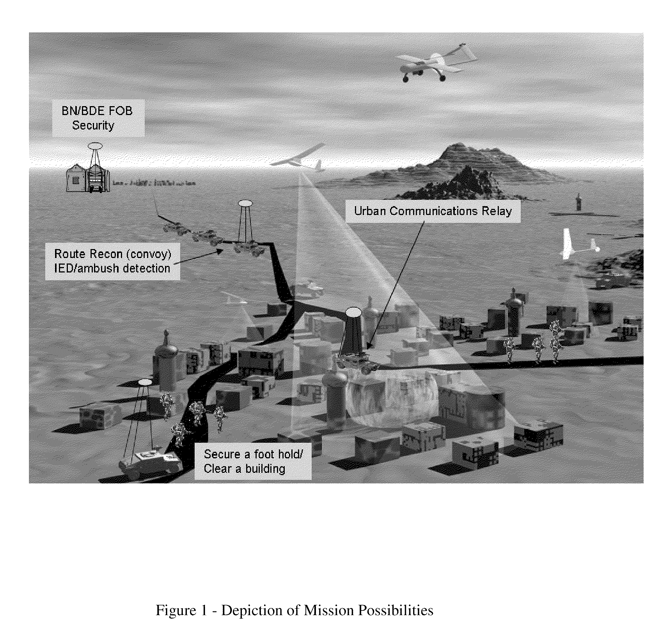
[0080]There exists a need in many different sectors of the military or government agencies for a small, user friendly, UAV that can hover above the user and provide an eye in the sky for surveillance and situational awareness. This need is documented in a presentation released by the US Army Infantry Center at Fort Benning Ga. and a Congressional Research Services report on the Army FCS on May 2008. The current UAVs on the market have mission profiles that have them flying through remote operator control or through complex autonomous operation. For many troops operating on the ground in places such as Iraq and Afghanistan, these vehicles are being used in ways that do not utilize their full operational envelope and are performing a mission an order of magnitude simpler than they were designed. For example, solders are using fully autonomous free flight UAVs to sit and hover in o...


PUM


Abstract

The design and refinement of a tethered hovering platform into a feasible working system is presented. To determine a starting point for the design, a detailed historical search was conducted to find the history and the current state of such technology. Real world current needs are analyzed to produce a mission specification and to drive the preliminary vehicle design. Analysis of environmental conditions and decisions about an initial payload package are made in conjunction with motor and propeller sizing. Initial concept testing to discover feasibility and operational issues was performed; from this, instability issues were discovered. Analyzing these instability issues using known rotorcraft and momentum effects, in conjunction with flight testing, yields possible solutions to the problem. The use of constrained layer dampers as a means of passive stabilization is addressed and suggested as the preferred solution. Testing of passive constrained layer damping verifies the stability of the solution. The system components and manufacturing cost is presented in comparison to current systems using active stabilization.

Description

CROSS-REFERENCE TO RELATED APPLICATION[0001]This application claims the benefit of and priority to U.S. Provisional Patent Application Ser. No. 61 / 110,526, filed Oct. 31, 2008, entitled TETHERED HOVERING PLATFORM, which application is hereby incorporated by reference to the extent permitted by law.BACKGROUND OF INVENTION[0002]1. Field of Invention[0003]This invention relates generally to tethered hovering platforms (THP), and more specifically to tethered hovering platforms utilizing composite material, lightweight motors and lightweight high strength tethers.[0004]2. Background Art[0005]Inventors attempting to perfect early helicopter designs used tethers to add stability and safety during testing and development. The idea of using tethers was re-visited by the Germans and the French in World War II. The German Navy successfully deployed the Fa 330, an un-powered helicopter towed behind submarines. In the decade after WWII designs of extremely large, unmanned, single and multiple t...

Claims


Application Information

Patent Timeline
Patent Type & Authority Patents(United States)
IPC IPC(8): B64F1/12B64C27/20B64C39/02
CPCB64C39/022B64C27/20B64C39/024B64C39/028B64C2201/027B64C2201/042B64C2201/108B64C2201/127B64C2201/148B64U2201/202B64U10/13B64U30/20B64U50/19B64U2101/30
Inventor BARRETT, RONALD M.BORYS, DAVID N.GLADBACH, ALEXGRORUD, DUSTINSPALDING, ANDREW
Owner UNIVERSITY OF KANSAS
Why Eureka
Try Eureka