Shrimp peeling machine and method and application

a peeling machine and shrimp technology, applied in the field of shrimp peeling machines, can solve the problems of inability to achieve optimal results, and inability to use known techniques, so as to achieve efficient peeling, improve the quality of finished products, and avoid freezing processes

Active Publication Date: 2014-07-15
VITTRUP THOMAS
View PDF10 Cites 8 Cited by
  • Summary
  • Abstract
  • Description
  • Claims
  • Application Information

AI Technical Summary

Benefits of technology

[0020]In this way it becomes possible to fine adjust the mutual position between the rollers, which shell the shrimps, whereby it becomes possible to make the shrimp peeling efficient, and to shell or peel shrimps without them passing angle sensitive skewed rollers, and the shrimp peeling machine can therefore be applied in shrimp trawlers whereby the shrimps can be peeled immediately after catch whereby a freezing process can be avoided.

Problems solved by technology

It has been found, however, that there are some drawbacks of this known technique, including that the efficiency of the shrimp peeling machine from U.S. Pat. No. 5,120,265 to an extensive degree is dependent on the angle, by which the parallel rollers are skewed.
This drawback, among others, results in that it has not been possible to use the known technique in shrimp trawlers since the trawlers' movement in the open sea will inevitably change the angle in relation to a horizontal level by which the parallel rollers are skewed.
The hitherto known technique has therefore in practice only functioned satisfyingly on land based production facilities.
It is obviously a drawback since the shrimps therefore must be frozen on the trawlers and then thawed when they must subsequently be peeled on the land-based shrimp peeling facilities.
Concurrently, the whole manufacturing process is allocated to two places namely partly on the fishing boats and partly on the land based shrimp peeling production facilities, which is not optimum.
It has been found, however, that the technique described in U.S. Pat. No. 2,832,092(A) does not function in a sufficiently efficient manner, including that it is not possible to adjust the mutual position between the rollers, which is used for shelling the shrimps.

Method used


Image

  • Shrimp peeling machine and method and application
  • Shrimp peeling machine and method and application
  • Shrimp peeling machine and method and application

Examples


Embodiment Construction

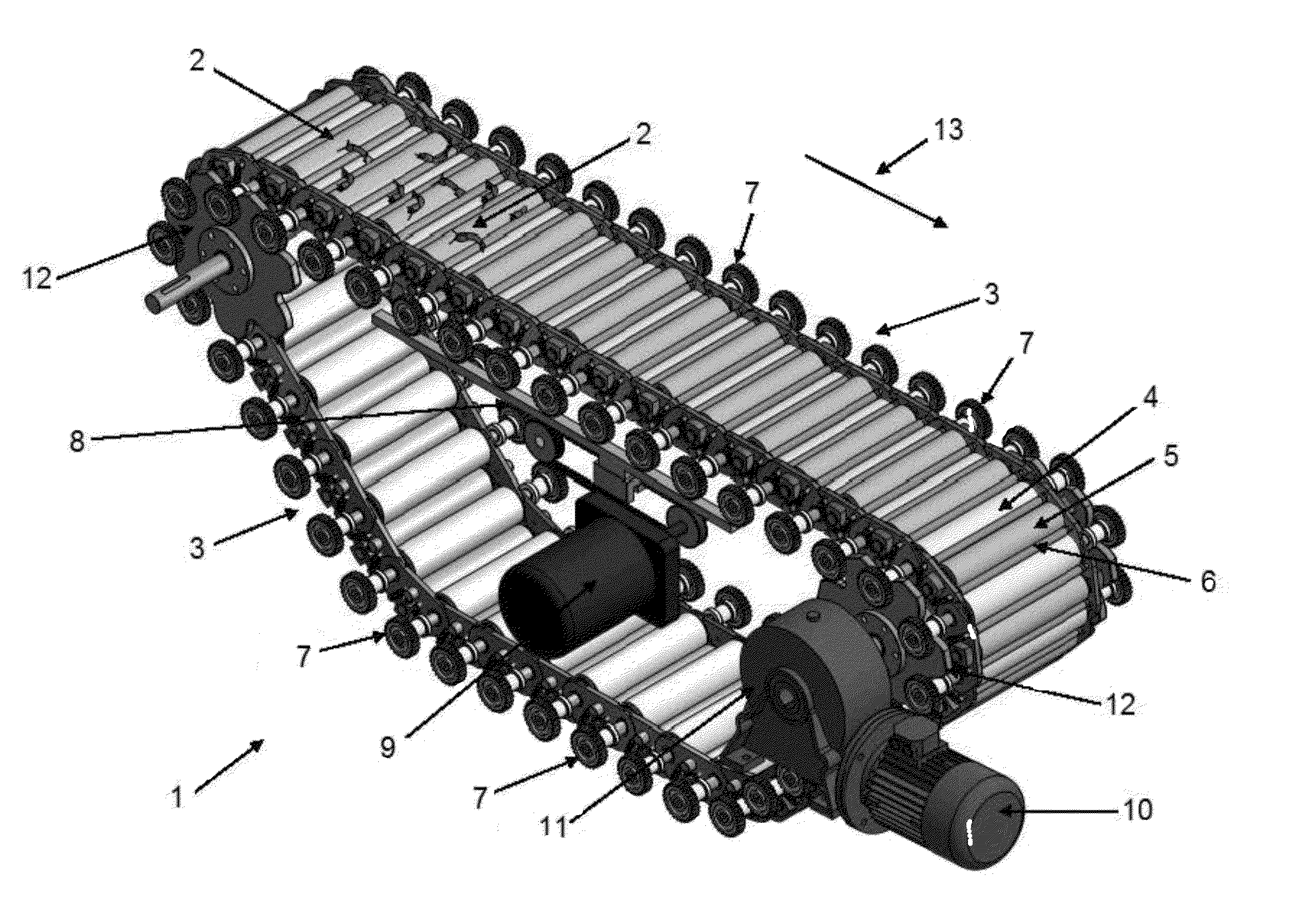
[0033]In FIG. 1 is shown a section of a shrimp peeling machine 1 where shrimp 2, which are to be peeled, are added to a closed chain 3 at the chain's 3 horizontal inlet in relation to a shrimp peeling process direction 13.

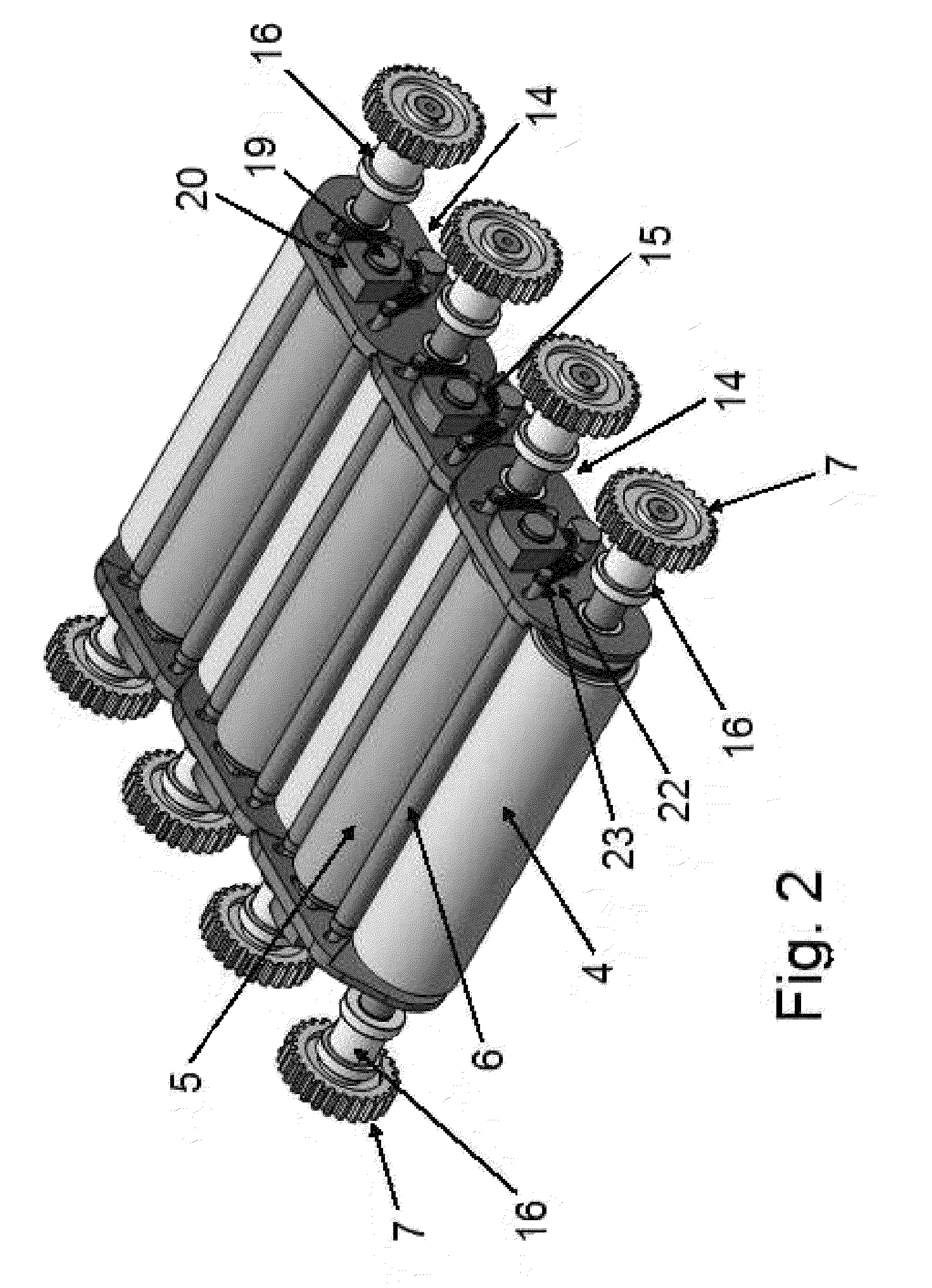
[0034]The shrimp peeling machine 1 is provided with a closed chain 3 consisting of a number of joints 14,15, which contain cylindrical rollers 4, 5, 6, where the cylindrical rollers' 4, 5, 6 longitudinal axis is displaced 90 degrees in relation to the shrimp peeling process direction 13 and where the rollers 4, 5, 6 can be turned by activation of toothed wheel 7 and where the chain 3 is operated by at least one toothed wheel 12, which is connected to a motor unit 10, 11.

[0035]The cylindrical rollers 4, 5, 6 have a metallic or a polymeric surface.

[0036]In a preferred embodiment, the cylindrical rollers 4, 5, 6 have at least two different diameters.

[0037]It is also a characteristic of the shrimp peeling machine 1 that toothed wheel 7, which operates the cylindrical r...


PUM


Abstract

A shrimp peeling machine (1) is provided with a closed chain (3) consisting of a number of joints (14,15), which contain cylindrical rollers (4, 5, 6). The cylindrical rollers' longitudinal axis is displaced 90 degrees in relation to the shrimp peeling process direction (13). The rollers can be turned by activation of toothed wheel (7), the chain operated by at least one toothed wheel (12), which is connected to a motor device (10,11). The rollers' mutual placement can be adjusted using position regulation guys (17). It is hereby achieved that the shrimp peeling machine, contrary to the hitherto known technique, can be mounted and function in shrimp trawlers. With the invention, in a continuous process, shrimp can be landed in a shrimp trawler and be boiled, peeled and packaged on the vessel and thus be ready for sale to the consumers, as soon as the trawler reaches harbour.

Description

CROSS REFERENCE TO RELATED APPLICATIONS[0001]This application is a National Stage of PCT International Application no. PCT / DK2012 / 00037, filed Apr. 11, 2012, claiming priority in Danish Patent Application no. PA 2011 00324, filed 27 Apr. 2011, the contents of which are hereby incorporated by reference.TECHNICAL FIELD[0002]The invention relates to a shrimp peeling machine for operation in stationary land based production facilities and in maritime production facilities including in fishing boats such as shrimp trawlers where the shrimp peeling occurs in a shrimp peeling process direction, where the shrimp peeling machine is provided with a closed chain consisting of a number of joints, which contains cylindrical rollers, where the longitudinal axis of the cylindrical rollers is displaced 90 degrees in relation to the shrimp peeling process direction and where the rollers can be turned by activation of toothed wheel and where the chain is operated by at least one toothed wheel, which ...

Claims


Application Information

Patent Timeline
Patent Type & Authority Patents(United States)
IPC IPC(8): A22C29/02
CPCA22C29/026
Inventor VITTRUP, THOMAS
Owner VITTRUP THOMAS
Why Eureka
Try Eureka