Heat exchanger having dehumidifying liquid and dehumidifier having the same

a heat exchanger and liquid technology, applied in the field of liquid type dehumidifying apparatus, can solve the problems of low heat and mass transfer coefficient, unstable liquid film, wave formation on the surface of liquid film, etc., and achieve the effect of enhancing the heat exchange efficiency and enhancing the strength of the extended surface plate against vertical deformation

Inactive Publication Date: 2014-07-29
KOREA INST OF SCI & TECH
View PDF8 Cites 36 Cited by
  • Summary
  • Abstract
  • Description
  • Claims
  • Application Information

AI Technical Summary

Benefits of technology

[0016]The extended surface plate may be formed to have a plurality of bending is portions in a horizontal direction, rather than to have the conventional linear shape. This may enhance an intensity against vertical deformation. The bending portions may be configured to have a corrugated form or a zigzag form.
[0018]For enhanced spreading of the dehumidifying liquid, the heat exchanging bodies may undergo a surface processing for enhanced wet property. Alternatively, a surface of the extended surface plate may undergo hydrophilic coating.
[0022]Secondly, an intensity of the extended surface plate against vertical deformation may be enhanced without using an additional reinforcing structure or without changing a material of the extended surface plate. This may enhance heat exchanging efficiency between the dehumidifying liquid and the air.

Problems solved by technology

This may lower a heat and mass transfer coefficient.
Furthermore, when a thick liquid film is formed on the surface of the heat exchanger, waves may be formed on the surface of the liquid film or the liquid film may become unstable.
This may cause the liquid film to be dispersed to the supplied air.
This may cause the heat exchanger to have a large size.
Furthermore, a heat transfer amount per unitary time is decreased due to a limited thickness of the liquid film.
This may cause the dehumidifying liquid not to uniformly spread onto the surfaces of the extended surface plates 50.
As a result, a contact area between the dehumidifying liquid and the air is decreased, and dehumidifying efficiency is degraded.
However, when the nonwoven fabric has a wet surface by the dehumidifying liquid, an intensity of the extended surface plate may be degraded due to a weight of the dehumidifying liquid.
However, this may cause the entire structure to become complicated, or degrade a wet property.

Method used


Image

  • Heat exchanger having dehumidifying liquid and dehumidifier having the same
  • Heat exchanger having dehumidifying liquid and dehumidifier having the same
  • Heat exchanger having dehumidifying liquid and dehumidifier having the same

Examples


Embodiment Construction

[0040]Description will now be given in detail of the exemplary embodiments, with reference to the accompanying drawings. For the sake of brief description with reference to the drawings, the same or equivalent components will be provided with the same reference numbers, and description thereof will not be repeated.

[0041]Hereinafter, a heat exchanger having an extended surface plate according to the present invention will be explained in more details with reference to the attached drawings.

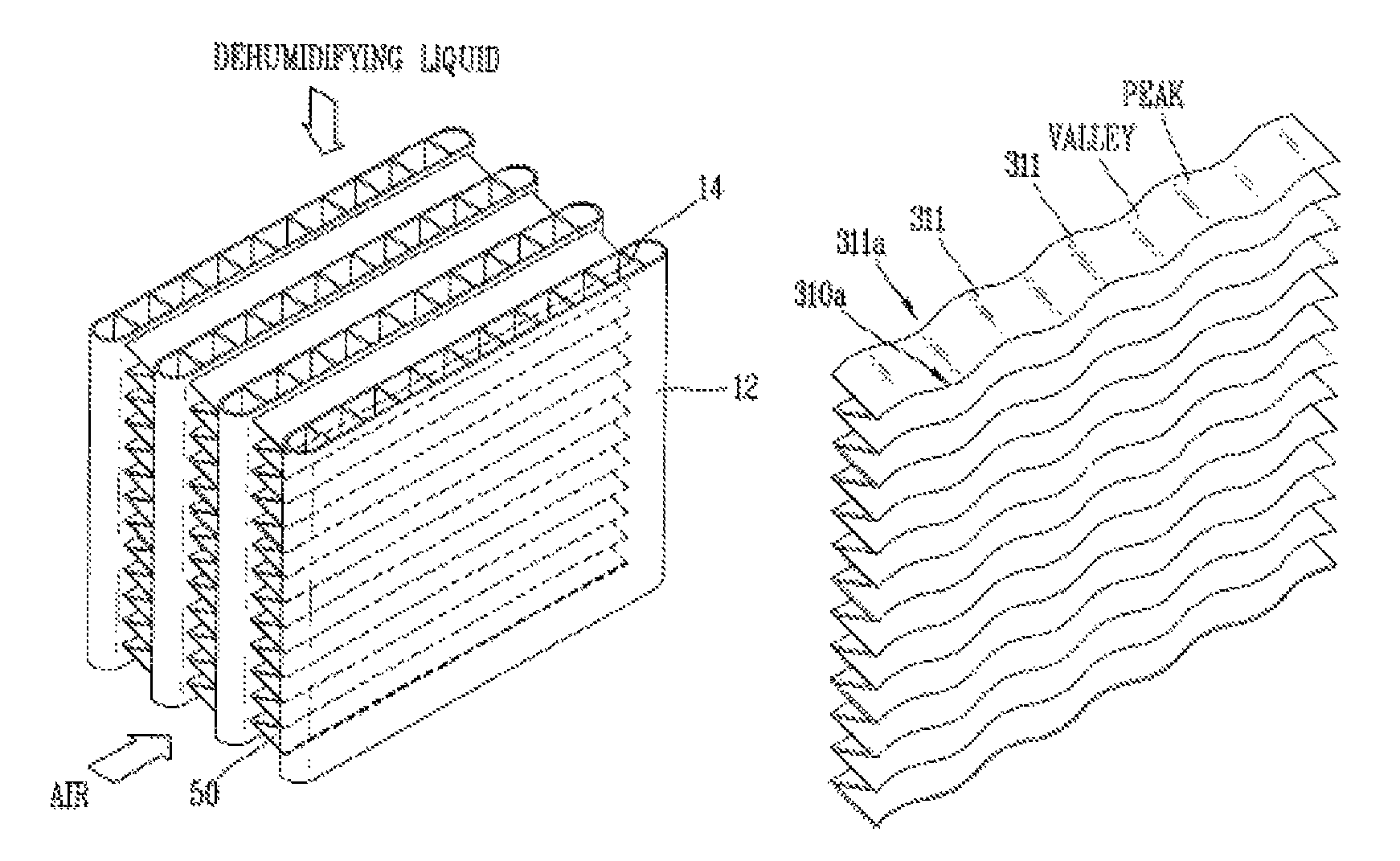
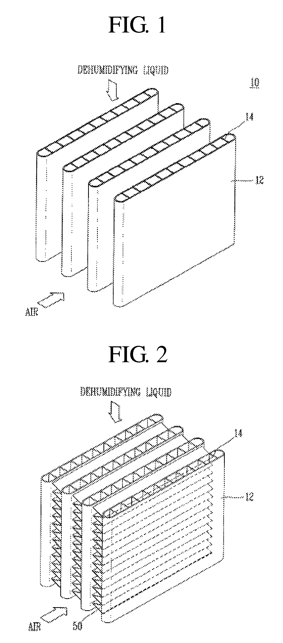
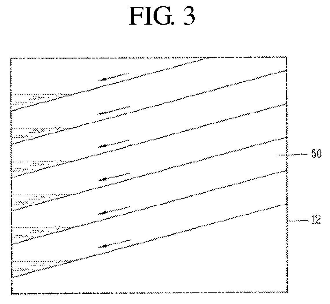
[0042]Referring to FIG. 4, a heat exchanger according to the present invention comprises a plurality of heat exchanging bodies 200, and an extended surface plate 300 disposed between the heat exchanging bodies 200. The heat exchanger may be a first heat exchanger 124 or a second heat exchanger disclosed in FIG. 4 or to be disclosed in the following descriptions.

[0043]The heat exchanging bodies 200 are disposed upright in parallel, and a predetermined space is formed therebetween. A flow path 210 al...


PUM

PropertyMeasurementUnit
hydrophilicaaaaaaaaaa
rigidityaaaaaaaaaa
concentrationaaaaaaaaaa

Abstract

A heat exchanger having an extended surface plate includes a plurality of heat exchanging bodies having therein flow paths along which a heat transfer medium flows, and extended surface plates each disposed between the heat exchanging bodies and having inclined surfaces in horizontal and vertical directions. Also disclosed is a dehumidifier having the heat exchanger. Moisture in the air may be effectively absorbed by a dehumidifying liquid, and the heat exchanger may have enhanced structural strength.

Description

CROSS-REFERENCE TO RELATED APPLICATION[0001]Pursuant to 35 U.S.C. §119(a), this application claims the benefit of earlier filing date and right of priority to Korean Application No. 10-2011-0031394, filed on Apr. 5, 2011, the contents of which is incorporated by reference herein in its entirety.BACKGROUND OF THE INVENTION[0002]1. Field of the Invention[0003]This specification relates to a liquid type dehumidifying apparatus, and particularly, to a heat exchanger having an extended surface plate capable of effectively absorbing moisture from the air by using a dehumidifying liquid, and capable of having enhanced rigidity, and a liquid type dehumidifier having the same.[0004]2. Background of the Invention[0005]Generally, a liquid type dehumidifier serves to obtain dry air by absorbing moisture in the air by spraying a dehumidifying liquid of a high concentration to the air. This liquid type dehumidifier is configured to perform consecutive dehumidifying operations by circulating the d...

Claims


Application Information

Patent Timeline
Patent Type & Authority Patents(United States)
IPC IPC(8): B01D53/14B01F3/04F28F3/00
CPCF28D3/02F24F3/1417F28D3/04F28D5/02F28D2021/0038F28F1/128F24F3/14F24F5/00
Inventor LEE, DAE-YOUNGKIM, SEO YOUNG
Owner KOREA INST OF SCI & TECH
Why Eureka
Try Eureka