Method and system for providing a magnetic recording transducer using a line hard mask and a wet-etchable mask

a technology of magnetic recording and hard mask, which is applied in the field of providing a magnetic recording transducer, can solve the problems of adverse effects on processing yield and performance, the inability of conventional magnetic transducers b>50/b> fabricated together on a wafer to be tested on a wafer level, and the inability to achieve the effect of reducing the cost of production

Inactive Publication Date: 2014-07-29
WESTERN DIGITAL TECH INC
View PDF45 Cites 129 Cited by
  • Summary
  • Abstract
  • Description
  • Claims
  • Application Information

AI Technical Summary

Problems solved by technology

As a result, processing yield and performance may be adversely affected.
Again, performance of the conventional magnetic transducer 50 may be adversely affected.
Consequently, conventional transducers 50 fabricated together on a wafer may not be able to be tested on a wafer level.

Method used


Image

  • Method and system for providing a magnetic recording transducer using a line hard mask and a wet-etchable mask
  • Method and system for providing a magnetic recording transducer using a line hard mask and a wet-etchable mask
  • Method and system for providing a magnetic recording transducer using a line hard mask and a wet-etchable mask

Examples


Embodiment Construction

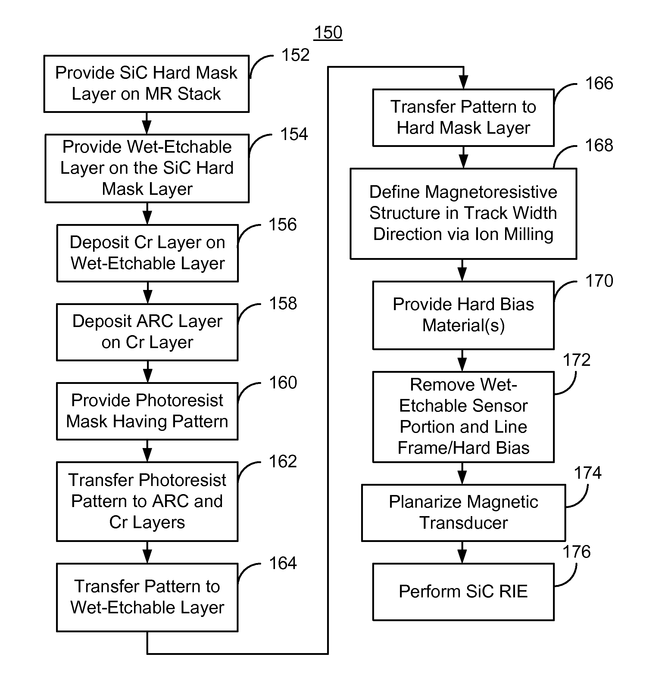
[0022]FIG. 5 is an exemplary embodiment of a method 100 for providing magnetic recording transducer. For simplicity, some steps may be omitted. The method 100 is also described in the context of providing a single recording transducer. However, the method 100 may be used to fabricate multiple transducers at substantially the same time. The method 100 is also described in the context of particular layers. A particular layer may include multiple materials and / or multiple sub-layers. The method 100 also may start after formation of other portions of the magnetic recording transducer. For example, the method 100 commences after deposition of magnetoresistive layer(s) for a magnetoresistive stack. The magnetoresistive layers may include a pinning layer, a pinned layer, a nonmagnetic spacer layer, and a free layer. In addition, seed and / or capping layers may be used. The pinning layer may be an AFM or other layer configured to fix, or pin, the magnetization of the pinned layer. The pinned...


PUM

PropertyMeasurementUnit
widthaaaaaaaaaa
thickaaaaaaaaaa
thickaaaaaaaaaa

Abstract

A method and system for fabricating a magnetic transducer is described. The transducer has device and field regions, and a magnetoresistive stack. Hard mask layer and wet-etchable layers are provided on the magnetoresistive stack and hard mask layer, respectively. A hard mask and a wet-etchable mask are formed from the hard mask and the wet-etchable layers, respectively. The hard and wet-etchable masks each includes a sensor portion and a line frame. The sensor portion covers part of the magnetoresistive stack corresponding to a magnetoresistive structure. The line frame covers a part of the magnetoresistive stack in the device region. The magnetoresistive structure is defined in a track width direction. Hard bias material(s) are then provided. Part of the hard bias material(s) is adjacent to the magnetoresistive structure in the track width direction. The wet-etchable sensor portion and line frame, and hard bias material(s) thereon, are removed.

Description

BACKGROUND[0001]FIG. 1 depicts a conventional method 10 for fabricating a magnetoresistive sensor in magnetic recording technology applications. FIGS. 2-4 depict a conventional transducer 50 during fabrication using the method 10. FIGS. 2-4 are not to scale. The method 10 typically commences after a conventional magnetoresistive, or MR, stack has been deposited.[0002]The conventional method 10 commences by providing a conventional hard mask layer, conventional pattern transfer layers, and a photoresist mask, via step 12. The conventional pattern transfer layers consist of a Cr layer and an antireflective coating (ARC) layer on the Cr layer. The conventional ARC layer aids in patterning of the conventional photoresist mask. The conventional photoresist mask has the desired pattern, which is transferred to the conventional ARC and Cr layers. The conventional photoresist mask covers the region from which the conventional magnetoresistive sensor is to be formed, as well as a line portio...

Claims


Application Information

Patent Timeline
Patent Type & Authority Patents(United States)
IPC IPC(8): G11B5/127G11B5/31G11B5/11
CPCG11B5/3903G11B5/112G11B5/3932G11B5/3116G11B5/3163
Inventor LUO, GUANGHONGYANG, DANNINGJIANG, MING
Owner WESTERN DIGITAL TECH INC
Why Eureka
Try Eureka