
Oxidation system with sidedraw secondary reactor

a secondary reactor and oxidation system technology, applied in the direction of furnaces, separation processes, liquid degasification, etc., can solve the problems of unfavorable oxidation rate, high capital cost of cstrs, and inability to produce impurities

Active Publication Date: 2014-07-29
GRUPO PETROTEMEX DE C V
View PDF12 Cites 7 Cited by
  • Summary
  • Abstract
  • Description
  • Claims
  • Application Information

AI Technical Summary

Benefits of technology

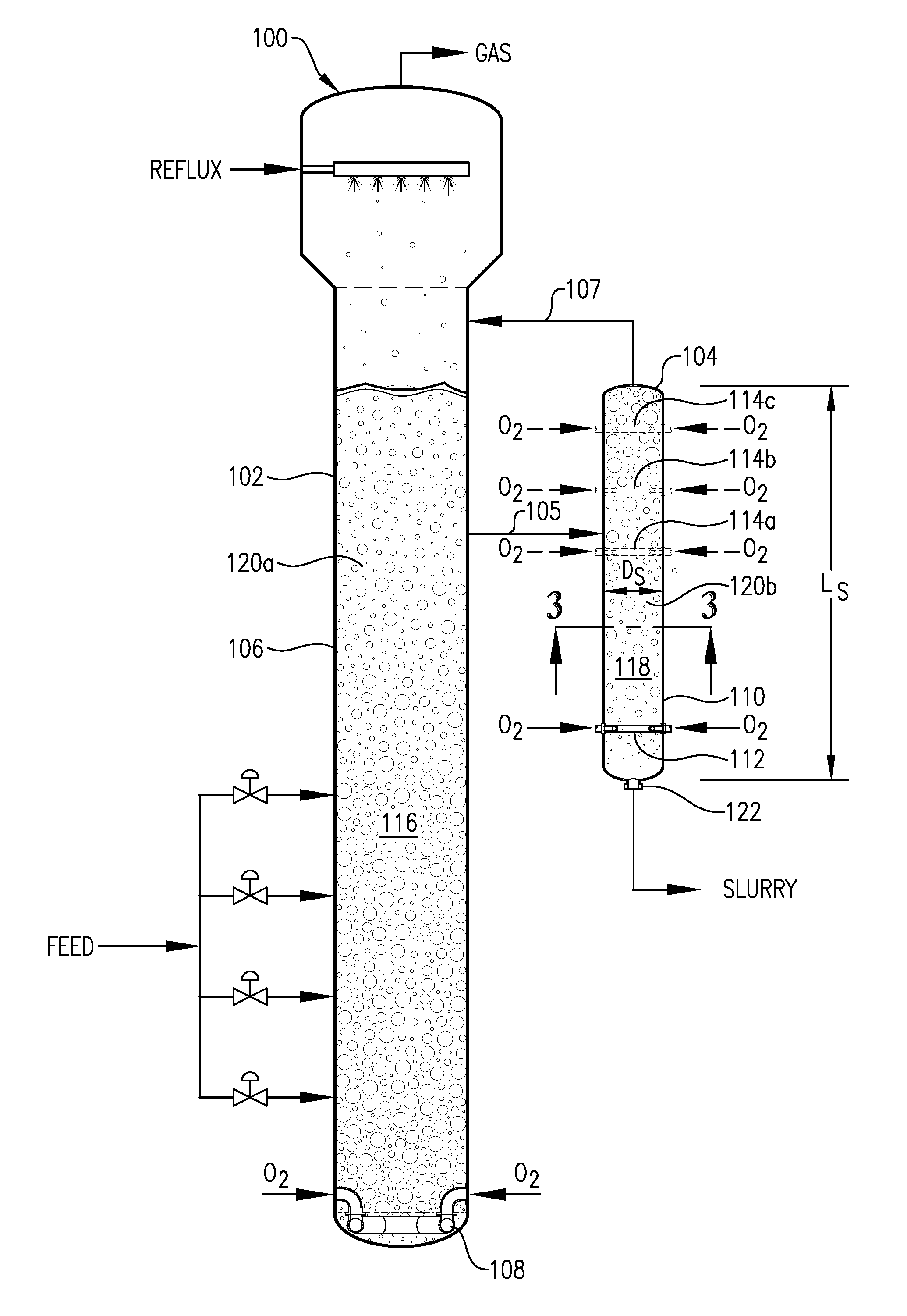
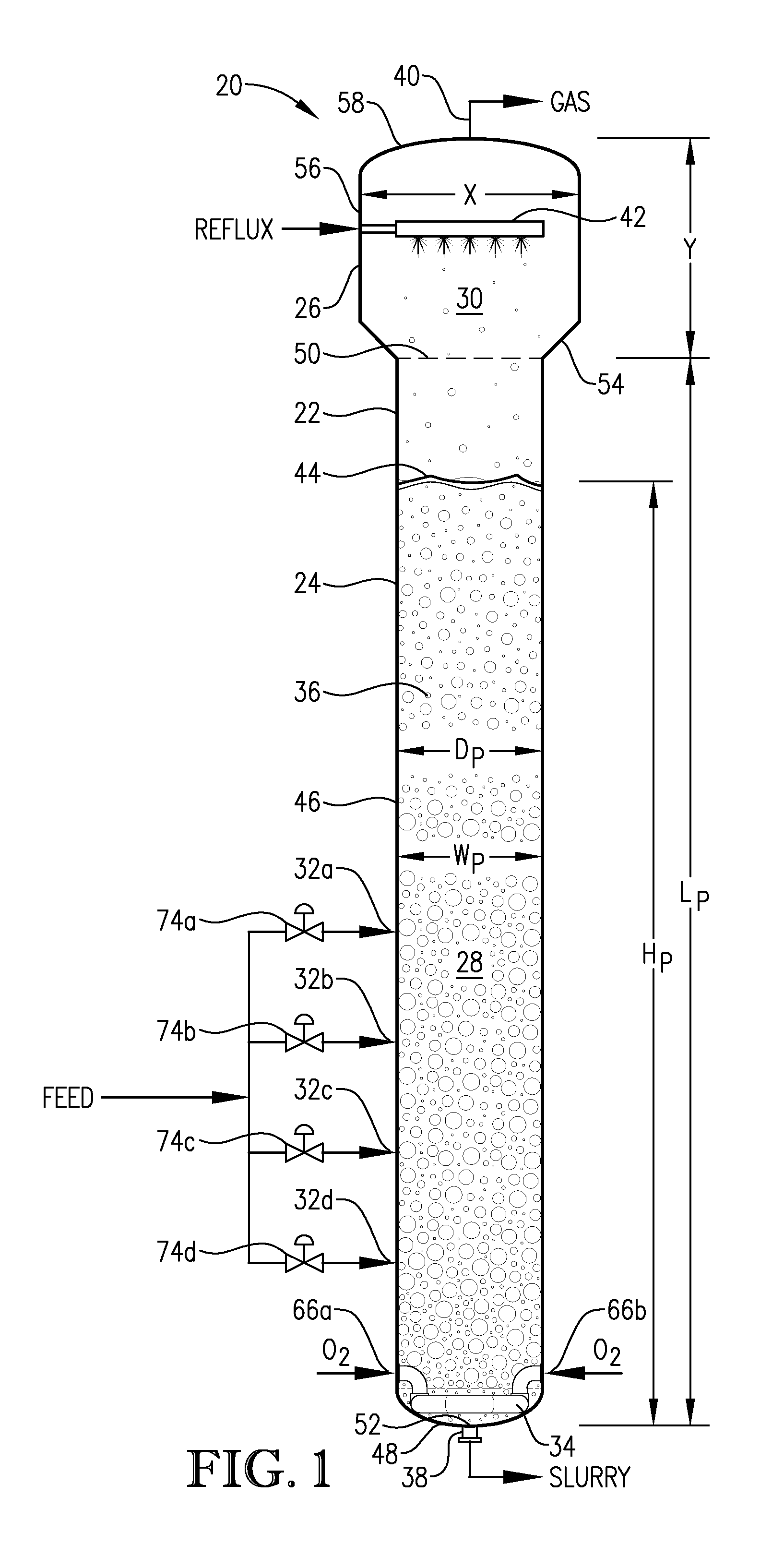
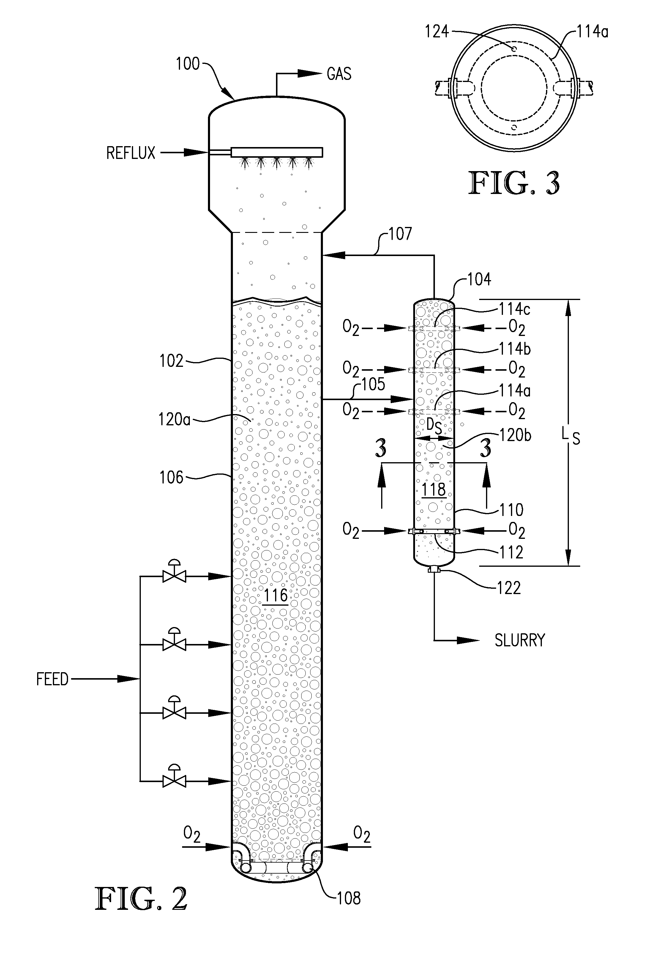
The present invention relates to a system and method for producing polycarboxylic acid. The system includes a primary oxidation reactor and a secondary oxidation reactor. In this embodiment, the secondary reactor has a maximum length Ls, and there is a normally lower oxidant inlet and a normally upper oxidant inlet. The method involves subjecting a multi-phase reaction medium to oxidation in the primary reactor to produce a first slurry, and then contacting at least a portion of the first slurry with gas-phase oxidant in the secondary reactor to produce a second slurry. The result is a higher yield of polycarboxylic acid.

Problems solved by technology

If the liquid phase of the multi-phase reaction medium contains an insufficient concentration of molecular oxygen (i.e., if certain portions of the reaction medium are “oxygen-starved”), undesirable side-reactions can generate impurities and / or the intended reactions can be retarded in rate.
If the liquid phase of the reaction medium contains too little of the oxidizable compound, the rate of reaction may be undesirably slow.
Further, if the liquid phase of the reaction medium contains an excess concentration of the oxidizable compound, additional undesirable side-reactions can generate impurities.
For example, CSTRs have a relatively high capital cost due to their requirement for expensive motors, fluid-sealed bearings and drive shafts, and / or complex stirring mechanisms.
Further, the rotating and / or oscillating mechanical components of conventional CSTRs require regular maintenance.
The labor and shutdown time associated with such maintenance adds to the operating cost of CSTRs.
However, even with regular maintenance, the mechanical agitation systems employed in CSTRs are prone to mechanical failure and may require replacement over relatively short periods of time.
CTA contains relatively high levels of impurities (e.g., 4-carboxybenzaldehyde, para-toluic acid, fluorenones, and other color bodies) that render it unsuitable as a feedstock for the production of PET.

Method used


Image

  • Oxidation system with sidedraw secondary reactor
  • Oxidation system with sidedraw secondary reactor
  • Oxidation system with sidedraw secondary reactor

Examples


Embodiment Construction

[0021]Various embodiments of the present invention concern the liquid-phase partial oxidation of an oxidizable compound. Such oxidation can be carried out in the liquid phase of a multi-phase reaction medium contained in one or more agitated reactors. Suitable agitated reactors include, for example, bubble-agitated reactors (e.g., bubble column reactors), mechanically agitated reactors (e.g., continuous stirred tank reactors), and flow agitated reactors (e.g., jet reactors). In one or more embodiments, the liquid-phase oxidation can be carried out using at least one bubble column reactor.

[0022]As used herein, the term “bubble column reactor” shall denote a reactor for facilitating chemical reactions in a multi-phase reaction medium, wherein agitation of the reaction medium is provided primarily by the upward movement of gas bubbles through the reaction medium. As used herein, the term “agitation” shall denote work dissipated into the reaction medium causing fluid flow and / or mixing....


PUM

PropertyMeasurementUnit
boiling pointaaaaaaaaaa

Abstract

Disclosed are process and apparatus for vertical splitting of the oxygen supply to a post-oxidation reactor. Further disclosed are process and apparatus for supplying reaction medium to a post-oxidation reactor at a mid-level inlet. Such apparatus and process can assist in reducing oxygen pinch throughout the post-oxidation reactor.

Description

CROSS-REFERENCE TO RELATED APPLICATIONS[0001]This application claims priority to the following three U.S. Provisional Application Serial Numbers: U.S. Provisional Application Ser. No. 61 / 299,450, filed Jan. 29, 2010, titled “OXIDATION SYSTEM WITH SIDEDRAW SECONDARY REACTOR;” U.S. Provisional Application Ser. No. 61 / 299,453, filed Jan. 29, 2010, titled “OXIDATION SYSTEM WITH SIDEDRAW SECONDARY REACTOR;” and U.S. Provisional Application Ser. No. 61 / 299,455, filed Jan. 29, 2010, titled “OXIDATION SYSTEM WITH SIDEDRAW SECONDARY REACTOR,” the disclosures of which are incorporated herein by reference in their entirety to the extent they do not contradict statements herein.BACKGROUND[0002]1. Field of the Invention[0003]This invention relates generally to a process for the production of a polycarboxylic acid composition. One aspect of the invention concerns the partial oxidation of a dialkyl aromatic compound (e.g., para-xylene) to produce a crude aromatic dicarboxylic acid (e.g., crude ter...

Claims


Application Information

Patent Timeline
Patent Type & Authority Patents(United States)
IPC IPC(8): B01J10/00B01J19/02B01J19/18C07C51/16C07C51/265
CPCB01J19/1862B01J19/1868B01J19/02B01J10/00C07C51/265B01J2219/00186C07C63/26
Inventor SHAIKH, ASHFAQLANGE, DAVID
Owner GRUPO PETROTEMEX DE C V
Learn More