Method of MR (=magnetic resonance) with spatial encoding to generate an image or spectroscopic data

a spatial encoding and magnetic resonance technology, applied in the field of magnetic resonance (= mr) with spatial encoding to generate images or spectroscopic data, can solve the problems of unsuitable current magnetic resonance imaging techniques, unnecessarily broadening magnetic resonance signals, and poor shape definition, so as to facilitate mr sequences and improve signal-to-noise ratios. , the effect of rapid signal acquisition

Inactive Publication Date: 2014-07-29
UNIVERSITATSKLINIKUM FREIBURG
View PDF7 Cites 5 Cited by
  • Summary
  • Abstract
  • Description
  • Claims
  • Application Information

AI Technical Summary

Benefits of technology

[0027]In yet another embodiment of the invention the preparing the nonlinear phase distribution step (c) and / or the effecting a primary spatial encoding step (d) is / are performed in either two or three dimensions. A three-dimensional approach facilitates MR sequences with improved signal-to-noise ratios, even though the design of a specific three-dimensional magnetic field is by far more complex.
[0028]In yet another embodiment of the invention the magnetic field used in step (c) and / or (d) is spatially variable and constant or variable in time, and the magnetic field is in particular being simultaneously applied during transmission of a radiofrequency (RF) pulse. This allows for a flexible preparation of the phase preparation and / or spatial encoding as well as a rapid signal acquisition.
[0031]In yet another embodiment of the invention, a technique is used to reduce spatial frequency aliasing artifacts from locations within the object of interest, the technique involving a multicoil reconstruction technique, in particular, SENSE, GRAPPA or the like. Hereby, aliasing artifacts from inconsistent or misplaced encoded signals can be eliminated by virtue of coil sensitivities.
[0034]According to another embodiment of the invention, acceleration techniques are used, the acceleration techniques making use of spatial frequency domain, in particular k-space (GRAPPA) or image space (SENSE) reconstructions. Thereby, acquisition of MRI or spectroscopic data can be further accelerated.

Problems solved by technology

Instead, the sample itself is moved within the static field, which, unfortunately, is unsuitable for current magnetic resonance imaging techniques, which have demands on patient positioning and comfort, as well as the ease of operator use.
Other disadvantages of these techniques is that they are isolated to the homogeneous center of the magnet, broaden magnetic resonance signals unnecessarily, are poorly defined in shape, or not used as an anti-aliasing method to increase scan resolution or further localization of signal in more than one dimension (topical magnetic resonance).
Apart from that, it is also difficult to manipulate or construct radiofrequency RF coils in such a way as to make a definite volume.
Some disadvantages, unique to the RF coil approach, are a) the non-uniformities of the radiofrequency field across the volume and b) the relatively long time necessary to apply the sequence of RF pulses and gradients that will localize the signal, during which the detectable signal can be lost and not recovered and the fact that c) shaped pulses used for localization may deposit too much electromagnetic radiation in human subjects.

Method used


Image

  • Method of MR (=magnetic resonance) with spatial encoding to generate an image or spectroscopic data
  • Method of MR (=magnetic resonance) with spatial encoding to generate an image or spectroscopic data
  • Method of MR (=magnetic resonance) with spatial encoding to generate an image or spectroscopic data

Examples


Embodiment Construction

Selecting a Volume of Interest within the Object of Investigation (Step a)

[0050]There are various ways to select volume of interests from within an object of investigation that are well known in the field of MR. The volume of interest may be selected with prior knowledge of the object's position, which may obtained from prior or ‘scout’ images. These scout images are typically very short duration, low resolution images obtained to determine the object's specific placement and orientation within the MRI apparatus. Alternatively, a volume of interest can be selected without this prior knowledge, in a fashion identical to the way the initial scout images are acquired.

Preparing a Transverse Magnetitzation with Nonlinear Phase Distribution

[0051]The transverse magnetization or signal in a MRI experiment is created by applying RF energy to the object in the neighborhood of the spin Larmor frequency. The equation for the transverse magnetization is given by
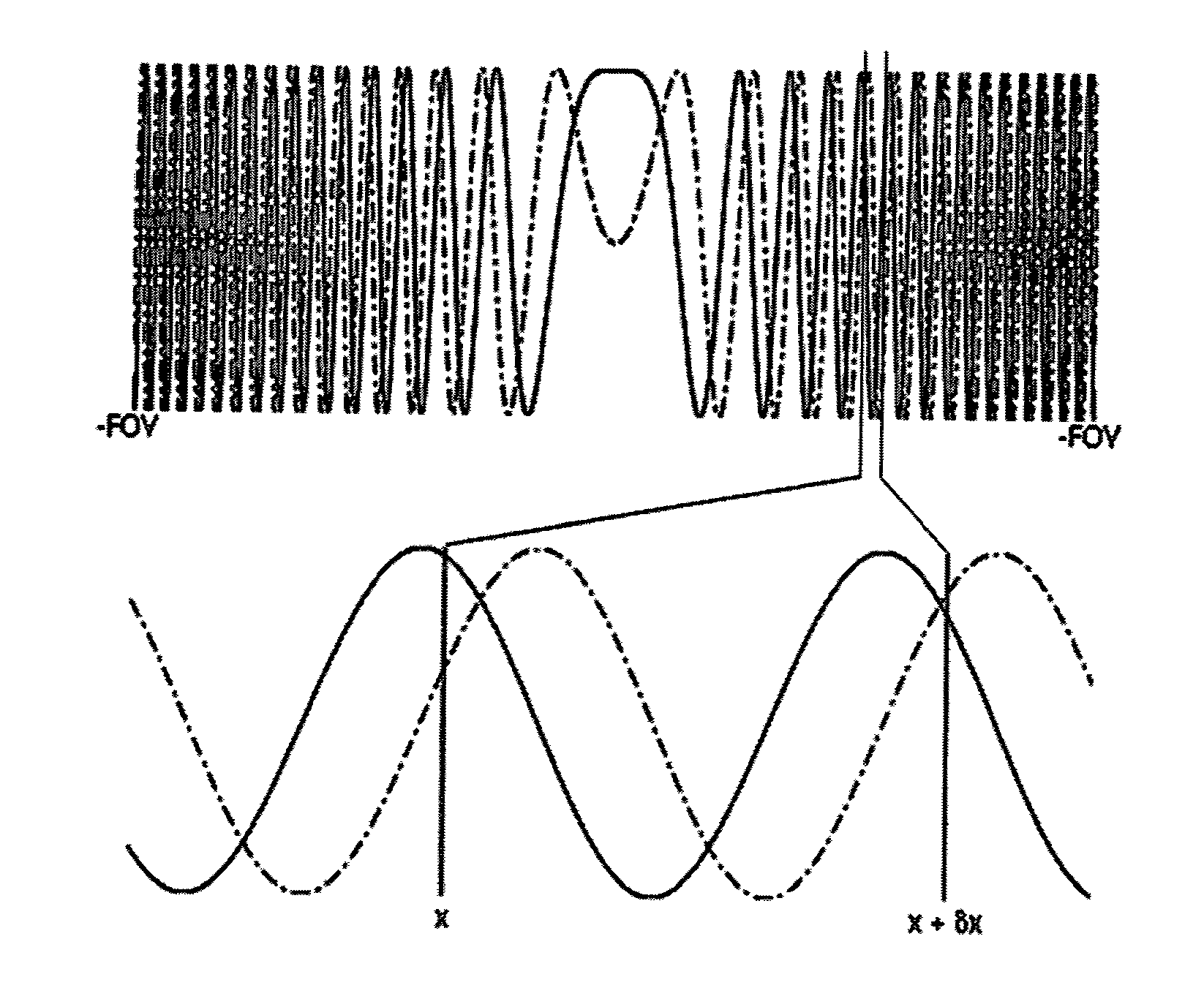
[0052]S⁡(t)=∫-∞∞⁢ρ⁡(x⇀)⁢ⅇⅈ⁢⁢ϕ⁢⁢(x⇀...


PUM


Abstract

A method of MR with spatial encoding to generate an image or spectroscopic data of an object of investigation inside an MR apparatus comprises the steps of (a) selecting a volume of interest within the object of investigation, (b) applying an RF pulse to generate a transverse magnetization within the object of investigation, (c) preparing a nonlinear phase distribution within the object of investigation by application of spatially encoding magnetic fields (SEMs), the SEMs comprising of a nonlinear gradient field or a combination of linear and nonlinear gradient fields, (d) effecting primary spatial encoding through application of SEMs, and (e) recording MR signals originating from the object of investigation. Step (c) or (d) thereby comprises applying a sequence of at least two SEMs, at least one of which contains a nonlinear field gradient and at least two of the SEMs having different field geometries. The sequence of SEMs is applied at a point in time from and including the excitation of the object of interest in step (b) up to and including the recording of the MR signals in step (e), to thereby introduce a temporal shift of the signals arising from spatially different locations within the selected volume of interest, that is to thereby introduce a shift of local spatial frequency components. A sampling window for recording of the respective MR signals is set and signals originating from the volume of interest are recorded in step (e) and undesired signals originating from outside the volume of interest are suppressed.

Description

[0001]This application claims Paris convention priority of EP 10 170 643.0 filed Jul. 23, 2010, the entire disclosure of which is hereby incorporated by referenceBACKGROUND OF THE INVENTION[0002]This invention relates to a method of magnetic resonance (=MR) with spatial encoding to generate an image or spectroscopic data of an object of investigation inside an MR apparatus comprising the steps of:[0003](a) selecting a volume of interest within the object of investigation;[0004](b) applying an RF pulse to generate a transverse magnetization within the object of investigation;[0005](c) preparing a nonlinear phase distribution within the object of investigation by application of spatially encoding magnetic fields (SEMs), the SEMs comprising a nonlinear gradient field or a combination of linear and nonlinear gradient fields;[0006](d) effecting primary spatial encoding through application of SEMs; and[0007](e) recording MR signals originating from the object of investigation.[0008]In MR ...

Claims


Application Information

Patent Timeline
Patent Type & Authority Patents(United States)
IPC IPC(8): G01V3/00G01R33/44
CPCG01R33/445G01R33/4833
Inventor WITSCHEY, WALTERGALLICHAN, DANIELZAITSEV, MAXIMSCHULTZ, GERRITHENNIG, JUERGEN
Owner UNIVERSITATSKLINIKUM FREIBURG
Why Eureka
Try Eureka