
Driven latch mechanism

a technology of latch mechanism and core barrel, which is applied in the direction of mechanical equipment, manufacturing tools, and borehole/well accessories, etc., can solve the problems of wedges and other problems, and achieve the effect of effective and efficient latching of the core barrel assembly, reducing or eliminating sliding contact (and associated wear), and reducing or eliminating wear

Active Publication Date: 2014-08-05
BOART LONGYEAR
View PDF104 Cites 12 Cited by
  • Summary
  • Abstract
  • Description
  • Claims
  • Application Information

AI Technical Summary

Benefits of technology

The driven latch mechanism effectively reduces wear between the core barrel assembly and the drill string by rotationally locking the core barrel, maintaining a secure latched position despite vibrations and inertial loads, and preventing unintentional movement or expulsion during drilling operations.

Problems solved by technology

Furthermore, rotation of the drill rod can cause the plurality of wedge members to rotationally lock the core barrel assembly relative to the drill rod.

Method used


Image

  • Driven latch mechanism
  • Driven latch mechanism
  • Driven latch mechanism

Examples


Embodiment Construction

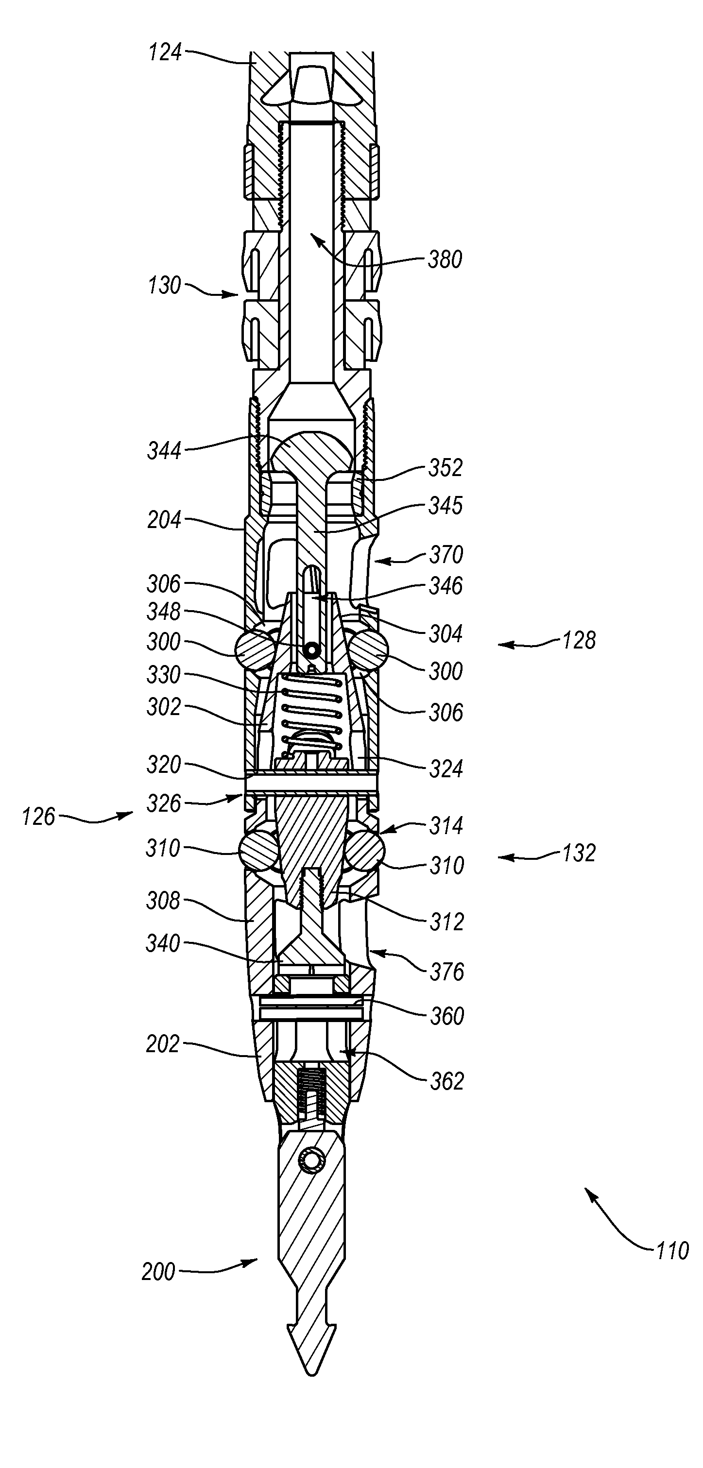
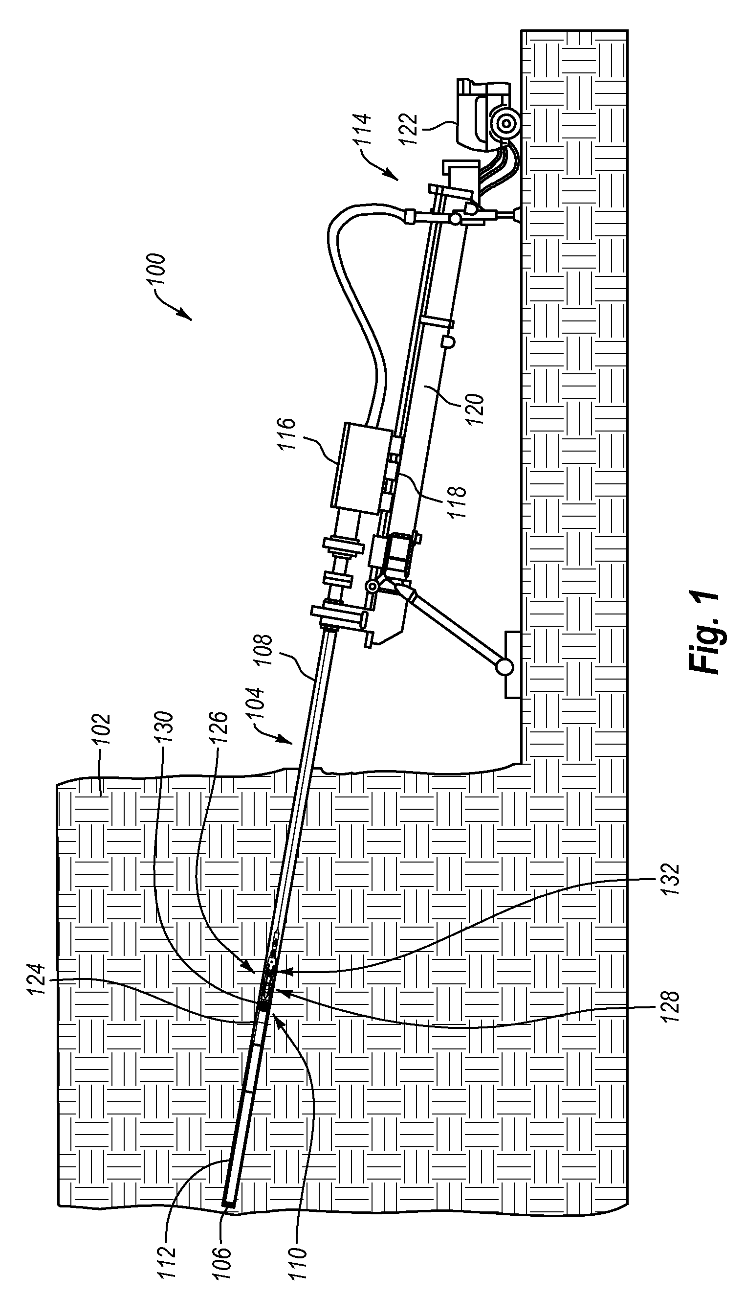
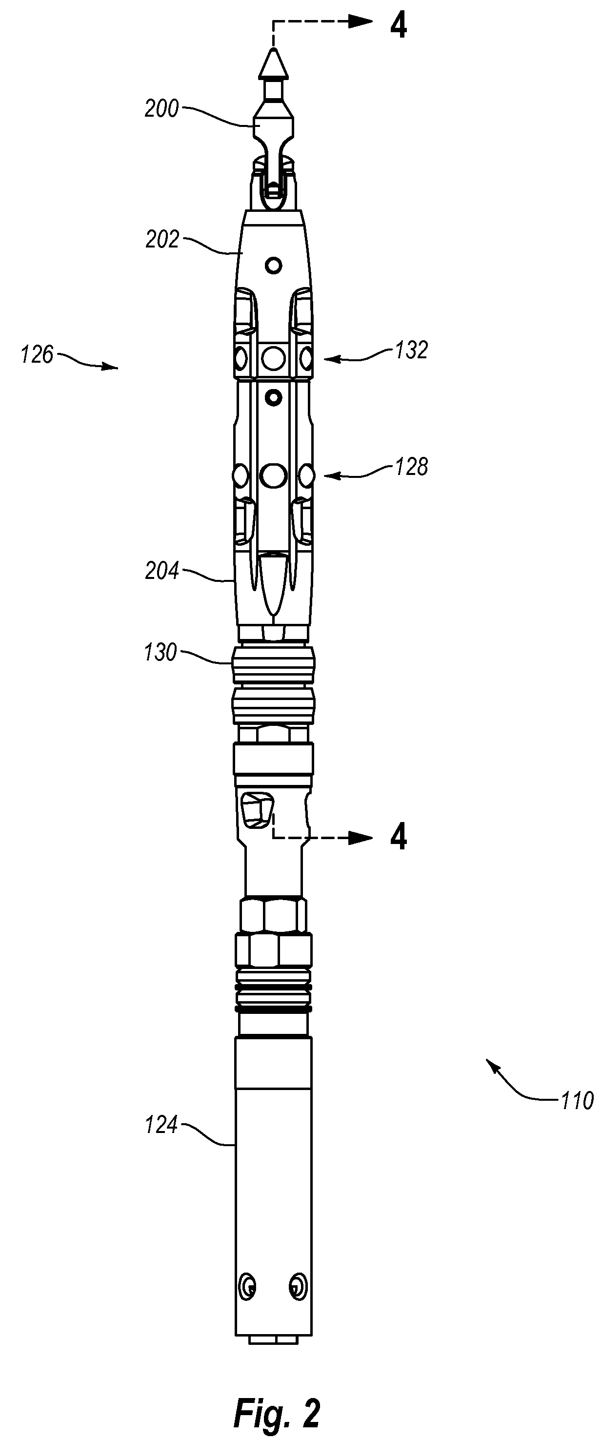
[0026]Implementations of the present invention are directed toward drilling tools, systems, and methods for effectively and efficiently latching a core barrel assembly to a drill string. For example, one or more implementations of the present invention include a core barrel assembly having a driven latch mechanism that can reliably lock the core barrel assembly in a fixed axial position within a drill string. Additionally, the drive latch mechanism can reduce or eliminate wear between mating components of the core barrel assembly and the drill string. In particular, the driven latch mechanism can rotationally lock the core barrel assembly relative to the drill string, thereby reducing or eliminating sliding contact (and associated wear) between mating components of the core barrel assembly and the drill string.

[0027]Assemblies, systems, and methods of one or more implementations can include or make use of a driven latch mechanism for securing a core barrel assembly at a desired posi...


PUM


Abstract

A core barrel assembly having a driven latch mechanism that can lock the core barrel assembly axially and rotationally relative to a drill string. The driven latch mechanism can include a plurality of wedge members positioned on a plurality of driving surfaces. Rotation of the drill string can cause the plurality of wedge members to wedge between an inner diameter of the drill string and the plurality of driving surfaces, thereby rotationally locking the core barrel assembly relative to the drill string. Drilling systems including the driven latch mechanism and methods of using the driven latch mechanism are also described.

Description

CROSS-REFERENCE TO RELATED APPLICATIONS[0001]This application claims priority to and the benefit of U.S. Provisional Application No. 61 / 249,544, filed Oct. 7, 2009, entitled “Driven Latch Mechanism.” This application also claims priority to and the benefit of U.S. Provisional Application No. 61 / 287,106, filed Dec. 16, 2009, entitled “Driven Latch Mechanism for High Productivity Core Drilling.” The contents of the above-referenced patent application are hereby incorporated by reference in their entirety.BACKGROUND OF THE INVENTION[0002]1. The Field of the Invention[0003]Implementations of the present invention relate generally to drilling devices and methods that may be used to drill geological and / or manmade formations. In particular, implementations of the present invention relate to core barrel assemblies and to mechanisms for latching core barrel assemblies to a drill string.[0004]2. The Relevant Technology[0005]Exploration drilling can include retrieving a sample of a desired ma...

Claims


Application Information

Patent Timeline
Patent Type & Authority Patents(United States)
IPC IPC(8): E21B10/02
CPCE21B49/02E21B25/02E21B23/02Y10T279/1045Y10T279/1091
Inventor DRENTH, CHRISTOPHER L.IONDOV, GEORGEIBRAHIM, GEORGE
Owner BOART LONGYEAR
Learn More