Devices and methods for treating valvular regurgitation

a technology of mitral valve and valve valve, applied in the field of mitral valve regurgitation treatment, can solve the problems of distorting the shape of the mitral valve, reducing the ejection volume and reducing the size of the left ventricle to compensate with a larger stroke volum

Active Publication Date: 2014-08-05
MEDTRONIC VASCULAR INC
View PDF11 Cites 42 Cited by
  • Summary
  • Abstract
  • Description
  • Claims
  • Application Information

AI Technical Summary

Problems solved by technology

This results in reduced ejection volume from the left ventricle, causing the left ventricle to compensate with a larger stroke volume.
However, the increased workload eventually results in dilation and hypertrophy of the left ventricle, further enlarging and distorting the shape of the mitral valve.
If left untreated, the condition may result in cardiac insufficiency, ventricular failure, and ultimately death.
This is a complex, invasive surgical procedure with the potential for many complications and a long recovery period.
Rigid annuloplasty rings have the disadvantage of causing the mitral valve annulus to be rigid and unable to flex in response to the contractions of the ventricle, thus inhibiting the normal, three dimensional movement of the mitral valve that is required for it to function optimally.
This eventually leads to scar tissue formation and loss of flexibility and function of the mitral valve.
Similarly, combination rings must generally be sutured in place and also cause scar tissue formation and loss of mitral valve flexibility and function.
While likely to be effective for modest changes in the size or shape of the mitral annulus, this device may cause significant tissue compression in patients requiring a larger change in the configuration of the mitral annulus.
Alternatively, the coronary sinus in a particular individual may not wrap around the heart far enough or may not be in an optimum position to allow effective encircling of the mitral valve, making this treatment ineffective.
Furthermore, leaving a device in the coronary sinus may result in formation and breaking off of thrombus that may pass into the right atrium, right ventricle, and ultimately the lungs causing a pulmonary embolism.
Another disadvantage is that the coronary sinus is typically used for placement of a pacing lead, which may be precluded with the placement of the prosthesis in the coronary sinus.

Method used


Image

  • Devices and methods for treating valvular regurgitation
  • Devices and methods for treating valvular regurgitation
  • Devices and methods for treating valvular regurgitation

Examples


Embodiment Construction

[0023]The invention will now be described by reference to the figures wherein like numbers refer to like structures. The terms “distal” and “proximal” are used herein with reference to the treating clinician during the use of the catheter system; “Distal” indicates an apparatus portion distant from, or a direction away from the clinician and “proximal” indicates an apparatus portion near to, or a direction towards the clinician.

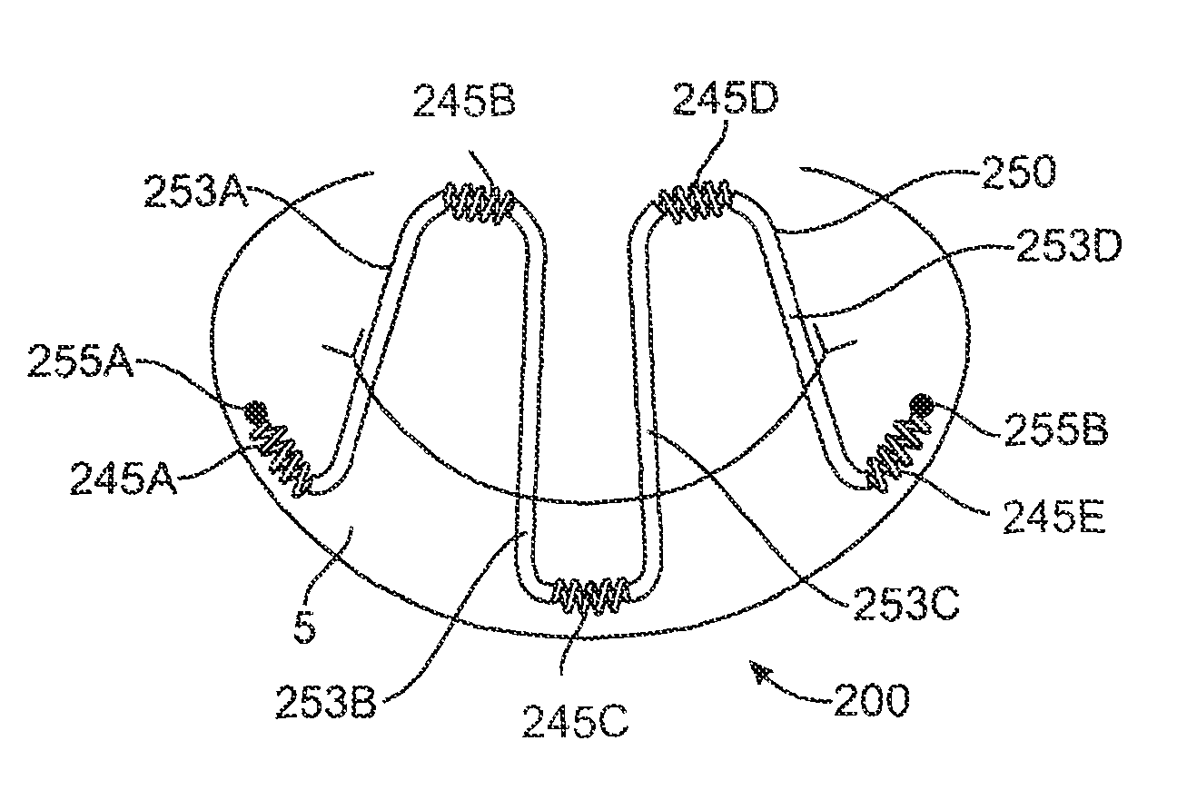
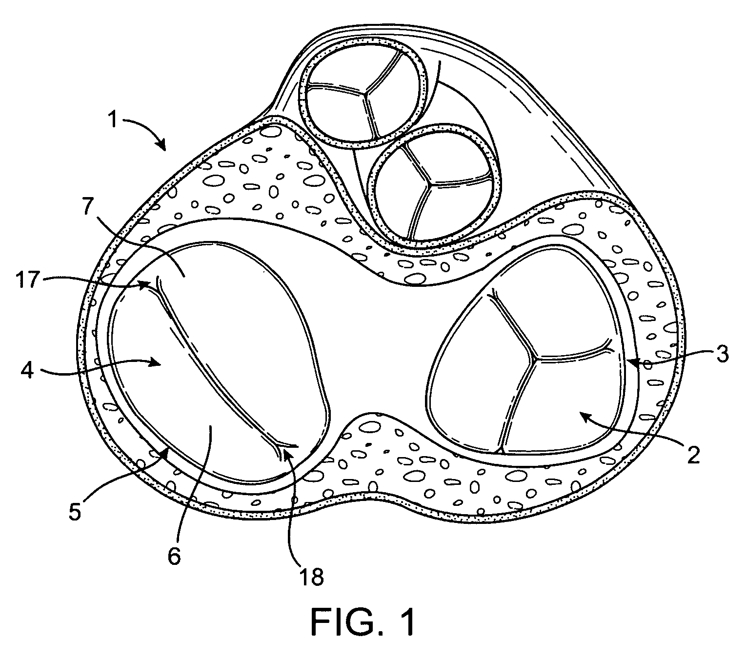
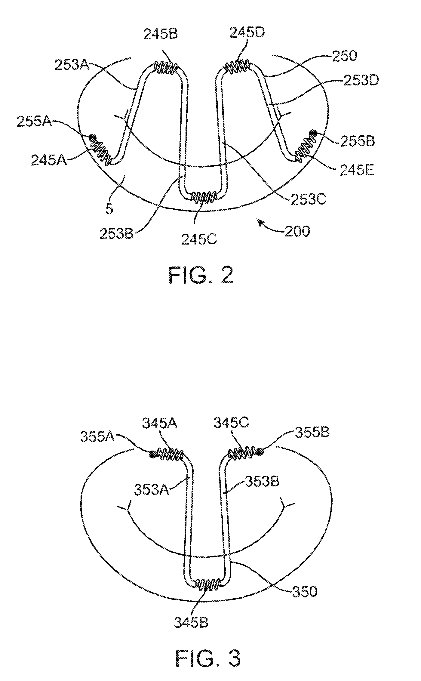
[0024]The current invention discloses devices and methods for treating regurgitation in cardiac valves. While these devices and methods are described below in terms of being used to treat mitral valve regurgitation, it will be apparent to those skilled in the art that the devices could be used on other cardiac valves, also. Tensioning devices of the current invention comprise helical anchors, at least one tension filament, and locks. The tensioning devices are used to modify the shape of heart valves for treating valvular regurgitation. The systems of the cur...


PUM


Abstract

A system for treating mitral valve regurgitation includes a tensioning device having a plurality of helical anchors and a tensioning filament. One embodiment of the invention includes a method for attaching a tensioning device to the annulus of a mitral valve in a trans-leaflet configuration, and applying a tension force to the tension filament in order to exert force vectors on the annulus, thereby reshaping the mitral valve annulus so that the coaption of the anterior and posterior leaflets of the mitral is improved during ventricular contraction.

Description

RELATED APPLICATIONS[0001]This application claims the benefit of, and priority to, U.S. Provisional Patent Application 61 / 045,021 filed on Apr. 15, 2008. The entirety of that application is incorporated herein by reference.FIELD OF THE INVENTION[0002]This invention relates generally to the treatment of mitral valve regurgitation and particularly to a method and device to improve mitral valve coaption in a diseased heart.BACKGROUND[0003]The heart is a four-chambered pump that moves blood efficiently through the vascular system. Blood enters the heart through the vena cava and flows into the right atrium. From the right atrium, blood flows through the tricuspid valve and into the right ventricle, which then contracts and forces blood through the pulmonic valve and into the lungs. Oxygenated blood returns from the lungs and enters the heart through the left atrium and passes through the mitral valve into the left ventricle. The left ventricle contracts and pumps blood through the aorti...

Claims


Application Information

Patent Timeline
Patent Type & Authority Patents(United States)
IPC IPC(8): A61F2/24
CPCA61F2/2466A61F2/2445A61B2017/0441A61B2017/0409A61B2017/00783A61F2/2427A61B2017/00243A61F2/2442A61B17/0487A61B2017/0496
Inventor O'BEIRNE, PATRICIARAFIEE, NASSER
Owner MEDTRONIC VASCULAR INC
Why Eureka
Try Eureka