Method for injecting a feed gas stream into a vertically extended column of liquid

a vertical extension and feed gas technology, applied in biomass after-treatment, biofuels, specific use bioreactors/fermenters, etc., can solve the problems of large quantities of gas required, complicated operation, energy-intensive gas discharging, etc., to achieve good gas dispersion, reduce surface tension, and profound effect on gas transfer efficiency

Active Publication Date: 2014-08-05
KLA SYST +1
View PDF13 Cites 4 Cited by
  • Summary
  • Abstract
  • Description
  • Claims
  • Application Information

AI Technical Summary

Benefits of technology

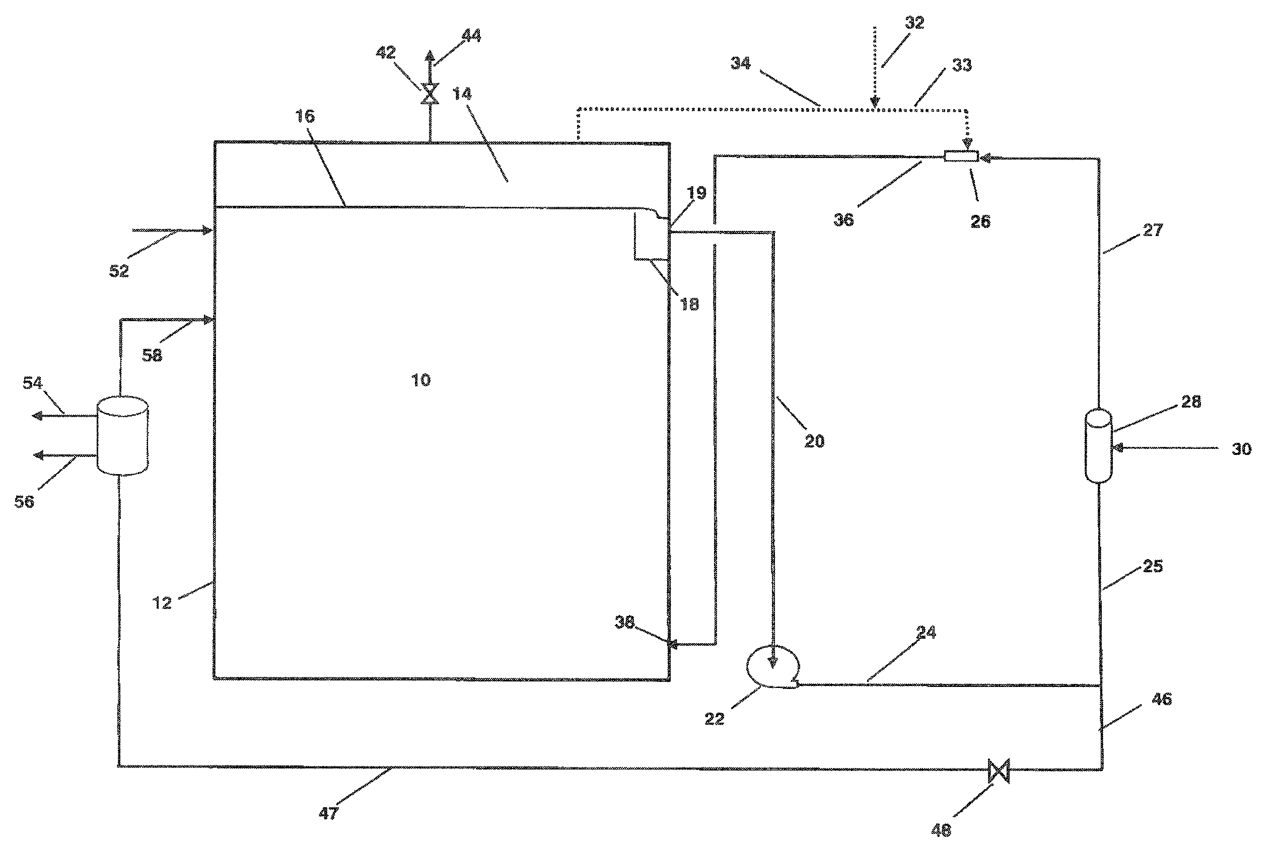
[0020]In particular the presence of alcohol in the fermentation liquid in conjunction with the use of gas injector allows the transport of the dispersion stream over a significant vertical distance without significant coalescing of the gas bubbles. Thus, the invention places the gas injector that creates the dispersion of gas and liquid at a relatively high elevation with respect to the elevation of the discharge point where the dispersion stream gets discharged into the liquid volume. Keeping the gas injector relatively higher than the point of discharge for the dispersion stream allows a lowering of the inlet pressure for the gas entering the gas injector.
[0021]The hydraulic head of liquid created by the injection of the dispersion stream into the vessel at a lower elevation than the gas injector eliminates the need for additional pressure on the outlet side of the gas injector. The downward transport of the dispersion stream in a confined conduit creates a static pressure head that compresses the dispersion stream before it enters the vessel. Injection of the feed gas into the fermentation liquid does lower the density of the gas-liquid dispersion relative to the fermentation liquid. Raising the outlet pressure of the gas injector can compensate for any loss in static pressure at the discharge point where the dispersion stream enters the fermentation vessel. The pressure of the dispersion stream at the discharge point may also be raised by elevating the gas injector location relative to the liquid level in the fermentation vessel. Elevating the gas injector adds net static pressure to the dispersion stream due to the increased height of the water column thereby increasing the pressure of the dispersion stream at the discharge point.
[0022]This raising of the gas injector elevation does not significantly increase the liquid side pressure required in the gas injector. As a result the gas phase still enters the gas injector at a relatively low pressure. The invention thereby eliminates or reduces the need for compression of the gas stream to the point where a compressor is not required. Instead, the pumping of the fermentation liquid as the motive fluid and the downward transport of the dispersion stream provides all of the necessary pressure to inject the gas-liquid dispersion into the fermentation vessel at a relatively low discharge point. In this manner the process effectively uses the height difference between the gas injector location and the discharge point to raise the pressure of the dispersion stream and eliminate the need for a compressor to supply feed gas to the process.
[0025]The method is enhanced by the presence of the product liquid in the fermentation broth that serves as a surface acting agent that lowers the surface tension to overcome the tendency of the bubbles to coalesce thereby avoiding loss of bubble / liquid interfacial area of the dispersed gas as it travels to a lower elevation of the discharge point. In particular it has been observed that the presence of oxygenates such as ethanol and / or organic acids such as acetic acid in the liquid media at concentrations as low as 0.05 wt % have a profound effect on gas transfer efficiency. In clean water the result of the adding the surface tension agent can provide gas transfer rates greater than 3 times that observed for clean water. Even at 0.05 wt % an increase of more than 50% in the gas transfer rate was observed. The combination of the alcohol as the surface acting agent together with the intense mixing at the elevated gas injector location gives the surprising result of sustaining good dispersion of the gas in liquid as it travels over distances in excess of 20 meters to the discharge point. Preferably the alcohol and / or organic acid is at a total concentration of at least 0.05 wt % and more preferably greater than 0.5 wt %.
[0026]The effect of the reduction in surface tension is the generation of smaller bubbles. The more finely divided dispersion of bubbles provides two benefits. The smaller bubbles provide a significantly greater surface area of gas bubbles exposed to the liquid. In addition the greater dispersion of gas compensates for any coalescence of the bubbles that occurs as the liquid-gas dispersion travels downward through the dispersion conduit to the discharge point.
[0028]This invention is particularly useful for the conversion of gas streams comprising components of syngas in a fermentation liquid. Ordinarily the fermentation liquid will comprise water, microorganisms suspended therein, nutrient chemicals, cell debris from the microorganisms and products produced by the metabolic processes of the microorganisms. The low solubility of the CO and H2 in the primarily aqueous fermentation liquid necessitates a very good dispersion of the gas into the liquid to achieve good mass transfer so that high conversion is efficiently obtained. The inherent presence of various organic compounds from such biological conversions, mostly ethanol, has been found to provide a highly beneficial combination in achieving good gas dispersion with the process arrangement of this invention.

Problems solved by technology

This dispersion of gas into liquid streams is energy intensive and typically requires compression of the gas stream to provide the necessary energy to create a high dispersion of gas in liquid phase contacting mediums.
And very large quantities of these gases are required.
These numerous reactors or bioreactors all suffer from various drawbacks in achieving the degree of mass transfer desired for optimum efficiency and productivity (mass of ethanol produced per unit volume-time).
The use of large compressors complicates the operation of such system which in turn adds to both the capital and operating expense of such operations.
Compressing a syngas stream poses special problems.
Derivation of the syngas from biological sources may leave residual materials in the syngas that challenge the operation of compressors.
Either of these materials can damage compressors that may be needed to create the necessary gas pressure to create high gas dispersion.

Method used


Image

  • Method for injecting a feed gas stream into a vertically extended column of liquid
  • Method for injecting a feed gas stream into a vertically extended column of liquid
  • Method for injecting a feed gas stream into a vertically extended column of liquid

Examples


example 1

[0071]This example shows the degree of gas dispersion obtained using water with a gas injector located proximate the top of a fermentation vessel that receives a low pressure gas input stream and produces a gas-liquid dispersion that travels downward for approximately 20 meters in a confined conduit for discharge into the bottom of the vessel. This example uses air as the low pressure gas input for health and safety reasons and measures dissolved oxygen in the liquid within the vessel to monitor gas transfer.

[0072]FIGS. 5 and 6 schematically depict the arrangement of the experimental apparatus for this example. A vessel 60 having a height of 21 meters and a diameter of 1.5 meters retained liquid to height of approximately 19 meters. The gas injector 62 was located at approximately the top of the vessel in a fiberglass reinforced plastic cross 64 having nominal pipe branch sizes of 15 cm×15 cm×15 cm×10 cm. A top pipe branch 66 of the cross having a 15 cm diameter retained the gas inj...

example 2

[0077]This example shows the feasibility of achieving high gas transfer and good gas dispersion using a gas injector located proximate the top of a fermentation vessel that receives a low pressure gas input stream and produces a gas-liquid dispersion that travels downward for approximately 20 meters in a confined conduit for discharge into the bottom of the vessel. The same test apparatus as depicted by FIGS. 5 and 6 and described in Example 1 was used in this Example 2. The liquid in the vessel and circulating through the system in this Example comprised water amended with approximately 500 mg / L of Ethanol and 500 mg / L of Acetic Acid (Amended Water). The amended water shows the effect of having a liquid product that reduces surface tension in a fermentation liquid. Conditions during the test period included a total liquid depth of 19 meters feet in the vessel, a temperature of 25.3° C. and barometric pressure of 738 mm Hg. Using a primary liquid flow rate of 320 liters per minute a...


PUM

PropertyMeasurementUnit
hydrostatic pressureaaaaaaaaaa
pressureaaaaaaaaaa
vertical lengthaaaaaaaaaa

Abstract

A process for conversion of syngas to liquid products that serve as surface acting agents uses the gas stream at a relatively low pressure to eliminate the use of a compressor. The process uses a liquid stream as the primary energy input to a gas injector that intensely mixes gas and the liquid with reduced compression costs while the presence of the liquid product maintains the gas-liquid dispersion as it flows downward to build a static pressure head. The process lowers the required gas pressure by adjusting the elevation of the gas injector such that a conduit receives the gas-liquid dispersion from the outlet of the injector and confines it as it travels downward to enter the bottom of a column of liquid. The liquid product provides a surface acting agent that prolongs the creation and duration of microbubbles in the gas-liquid dispersion.

Description

FIELD OF THE INVENTION[0001]This invention relates to the mixing of a feed gas comprising CO, CO2, and H2 with a liquid medium comprising an aqueous alcohol stream to create a fine dispersion of feed gas in a liquid phase conversion zone comprising a deep fermentation vessel.DETAILED DESCRIPTIONBackground[0002]The conversion of gas stream components by contact with a conversion medium in a liquid phase is well practiced in many fields. Where the solubility of the gas stream is limited, contacting and conversion of the gas stream components requires that the gas stream be well disbursed within the liquid medium as a fine dispersion to increase the mass transfer between the gas phase and the conversion media in the liquid phase. This dispersion of gas into liquid streams is energy intensive and typically requires compression of the gas stream to provide the necessary energy to create a high dispersion of gas in liquid phase contacting mediums.[0003]A wide variety of devices are known ...

Claims


Application Information

Patent Timeline
Patent Type & Authority Patents(United States)
IPC IPC(8): C12P7/06C12M1/00C12P7/00C12P7/02C12P7/04C12P7/16
CPCC12P7/065C12M29/06Y02E50/17Y02E50/10C12P7/06C12P7/16C12P7/52C12P7/54
Inventor HICKEY, ROBERTNEVILLE, MARK
Owner KLA SYST
Why Eureka
Try Eureka