
Organic light emitting diode display and stereoscopic image display using the same

a light-emitting diode and organic light-emitting diode technology, applied in the field of stereoscopic image display, can solve the problems of reducing the luminance of a 3d image, difficult to secure a sufficient opening time of the left and right eye shutters stl and str, and affecting the effect of the image quality of the image, so as to reduce the effect of 3d crosstalk and minimize the effect of luminance reduction

Active Publication Date: 2014-08-05
LG DISPLAY CO LTD
View PDF7 Cites 4 Cited by
  • Summary
  • Abstract
  • Description
  • Claims
  • Application Information

AI Technical Summary

Benefits of technology

This patent is about improving OLED displays by reducing 3D crosstalk, minimizing luminance reduction, compensating for changes in anode voltage, and performing a high-speed driving method. The patent includes a second idle period between the programming and emission periods, which increases by delaying the start time points of the emissions and gate pulses. The control circuit sequentially scans the gates and addresses the left and right eye image data to the pixels during the second period. The emission pulse is then scanned from a middle time point to an end time point during the second period, while the light emitting time of the pixels overlaps a second half period of the second period. The control circuit also allows the left eye shutter to be opened during the third period of the left eye frame and the right eye shutter to be opened during the third period of the right Eye frame. The technical effect of this patent is to improve the quality of OLED displays.

Problems solved by technology

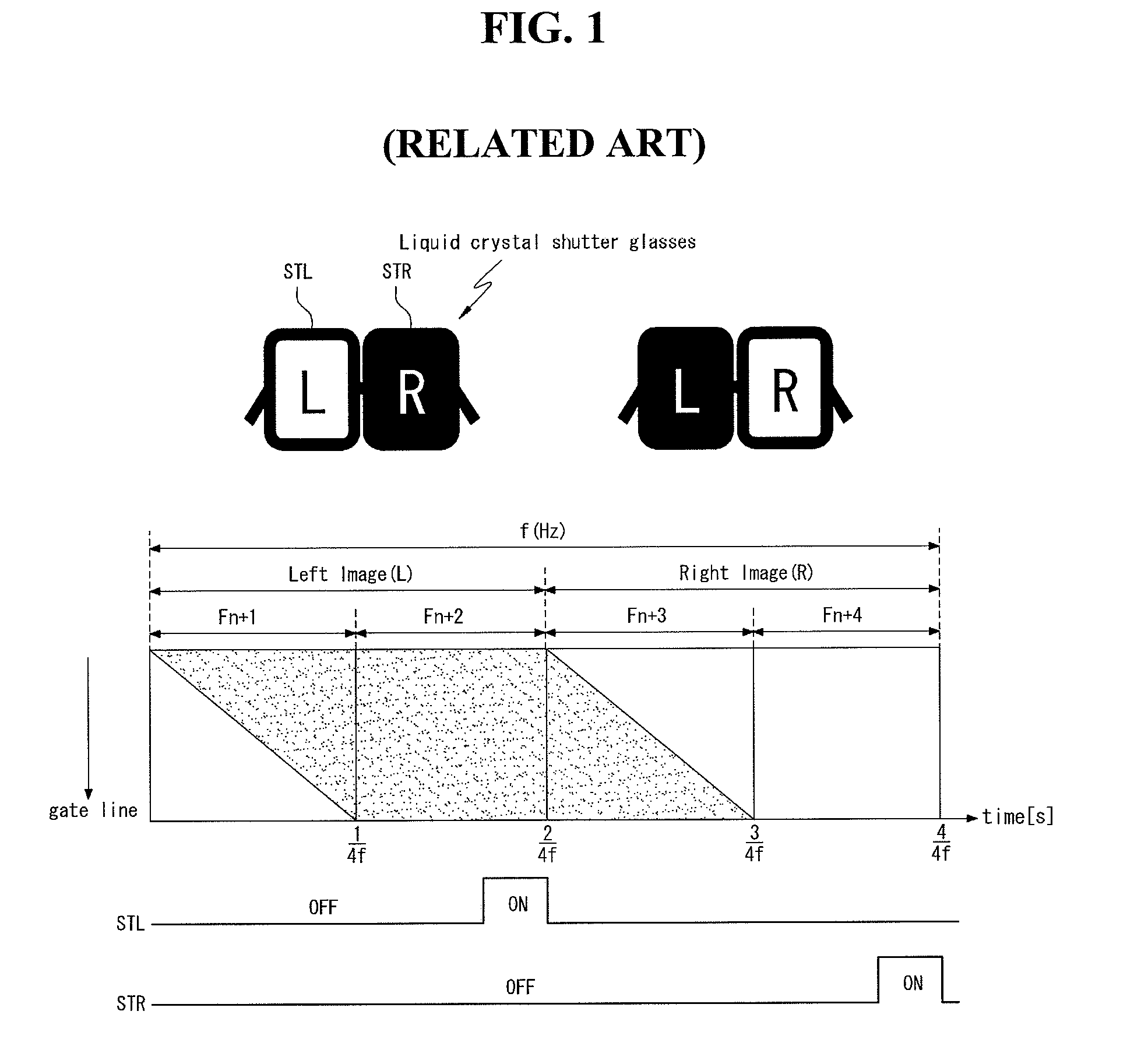
However, 3D crosstalk seen as ghost images occurs in the liquid crystal display because of a slow response time of the liquid crystals at a time when the left eye image changes into the right eye image or at a time when the right eye image changes into the left eye image.
Although the high-speed driving method is adopted, it is difficult to secure a sufficient opening time of the left and right eye shutters STL and STR because of a slow response time of the liquid crystals.
Therefore, the stereoscopic image display using the liquid crystal display as the display device greatly reduces a luminance of a 3D image when the 3D image is implemented.
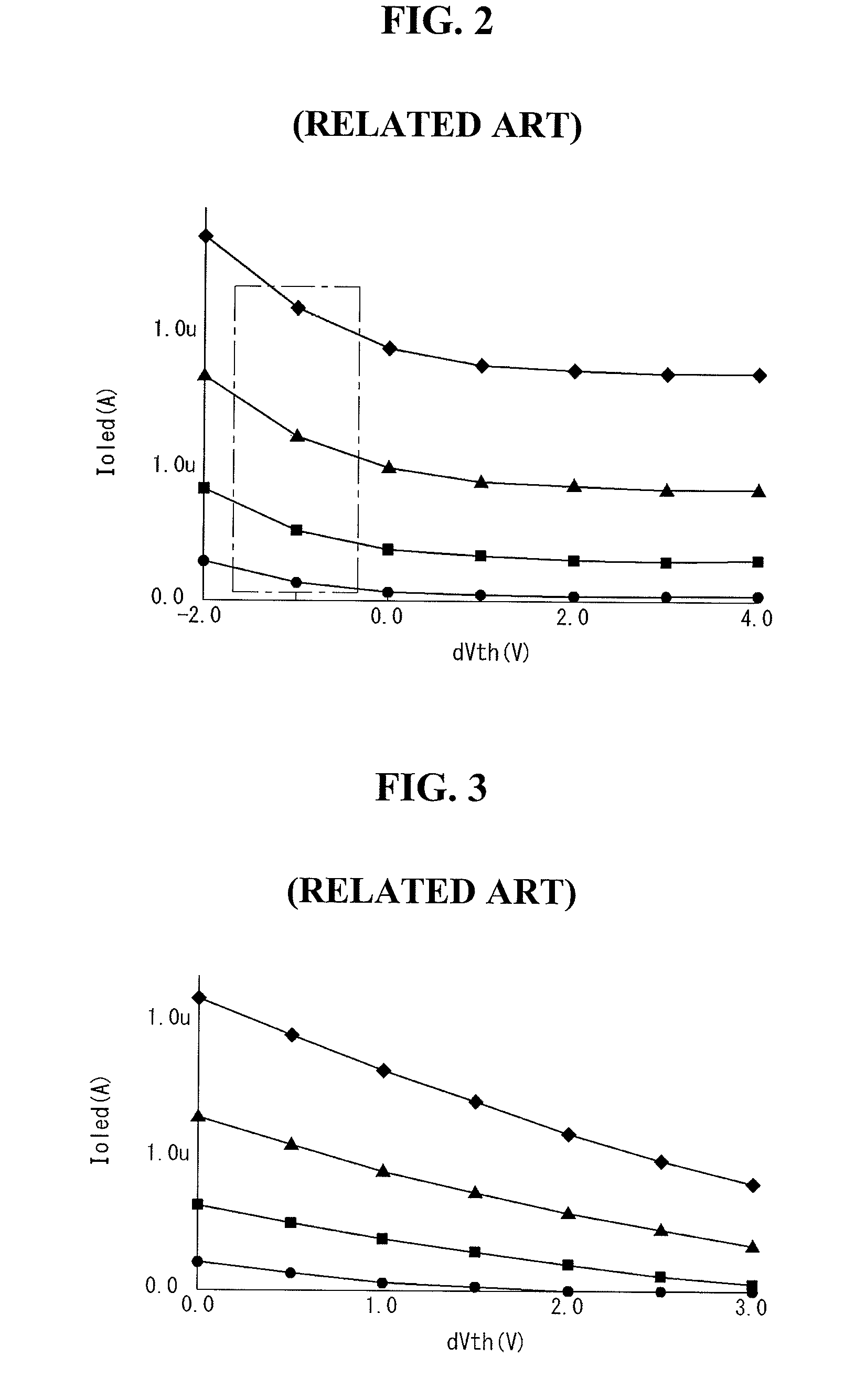
Firstly, a driving current Ioled determining a light emission luminance of the OLED of the OLED display greatly varies when a threshold voltage Vth of the driving TFT varies as shown in FIG. 2, and when a potential of a low potential driving voltage Vss varies as shown in FIG. 3. The threshold voltage Vth of the driving TFT is shifted to the positive or negative direction due to a gate-bias stress or element characteristic. The positive shift of the threshold voltage Vth may be compensated using a known diode-connection method. However, it is difficult to compensate for the negative shift of the threshold voltage Vth using the known diode-connection method. The potential of the low potential driving voltage Vss varies because of a RC delay inside the display panel. A difference between the threshold voltages Vth of pixels and / or a difference between the low potential driving voltages Vss of the pixels cause a luminance difference between the pixels, thereby degrading the display quality of the stereoscopic image display.
Secondly, as shown in FIG. 4, the OLED display applies a data voltage Vdata to a gate electrode of the driving TFT and also compensates for the threshold voltage Vth of the driving TFT during a period T (i.e., a high logic period of a gate pulse), in which a switching TFT connected to the driving TFT is turned on. In the OLED display, one vertical period is determined by a frame frequency. Therefore, as the frame frequency increases, a turn-on period T of the switching TFT decreases. A reduction in the turn-on period T of the switching TFT results in a reduction in a charging period of the data voltage Vdata, thereby causing the bad charge. Further, a reduction in a compensation period of threshold voltage Vth of the driving TFT results in the bad compensation. It is difficult to adopt the high-speed driving method to the related art OLED display because of these reasons.

Method used


Image

  • Organic light emitting diode display and stereoscopic image display using the same
  • Organic light emitting diode display and stereoscopic image display using the same
  • Organic light emitting diode display and stereoscopic image display using the same

Examples


Embodiment Construction

[0044]Reference will now be made in detail to the specific embodiments of the present invention, examples of which are illustrated in the accompanying drawings. Wherever possible, the same reference numbers will be used throughout the drawings to refer to the same or like parts. It will be paid attention that detailed description of known arts will be omitted if it is determined that the arts can mislead the present invention.

[0045]Example embodiments of the present invention will be described with reference to FIGS. 5 to 17.

[0046]FIGS. 5 and 6 illustrate a stereoscopic image display according to an example embodiment of the invention. FIG. 7 illustrates a control circuit shown in FIG. 5.

[0047]As shown in FIGS. 5 and 6, the stereoscopic image display according to the example embodiment of the invention uses an organic light emitting diode (OLED) display as a display device. The stereoscopic image display according to the example embodiment of the invention includes display devices 1...


PUM


Abstract

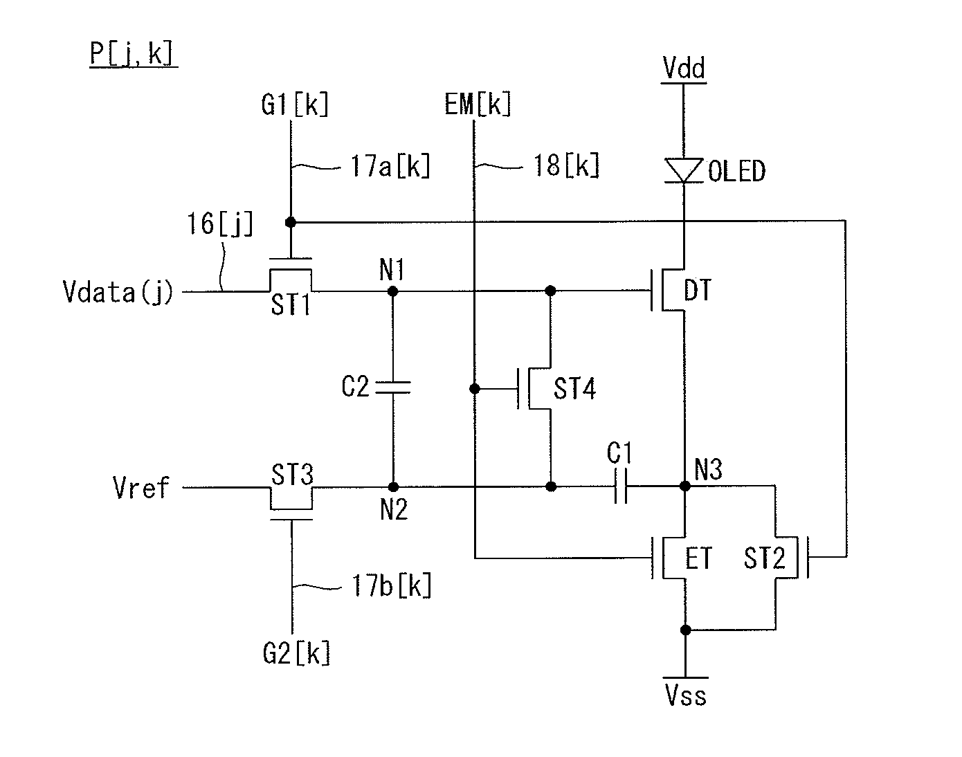
An organic light emitting diode (OLED) display and a stereoscopic image display using the OLED display are disclosed. The stereoscopic image display includes a display panel, which includes a plurality of pixels and displays left eye image data and right eye image data in a time division manner, liquid crystal shutter glasses including a left eye shutter and a right eye shutter, which are alternately opened and closed in synchronization with the display panel, a data driver for driving data lines of the display panel, and a gate driver for sequentially supplying a plurality of pairs of gate pulses to a plurality of pairs of gate lines of the display panel. Each of the pixels includes an OLED, a driving thin film transistor (TFT), first to fourth switch TFT, an emission TFT, and first and second capacitors.

Description

[0001]This application claims the benefit of Korean Patent Application No. 10-2010-0082938 filed on Aug. 26, 2010, which is incorporated herein by reference for all purposes as if fully set forth herein.BACKGROUND OF THE INVENTION[0002]1. Field of the Invention[0003]Embodiments of the invention relate to a stereoscopic image display capable of implementing a three-dimensional stereoscopic image (hereinafter referred to as ‘3D image’).[0004]2. Discussion of the Related Art[0005]A stereoscopic image display implements a 3D image using a stereoscopic technique or an autostereoscopic technique.[0006]The stereoscopic technique, which uses a parallax image between left and right eyes of a user with a high stereoscopic effect, includes a glasses type method and a non-glasses type method, both of which have been put to practical use. In the non-glasses type method, an optical plate such as a parallax barrier for separating an optical axis of the parallax image between the left and right eye...

Claims


Application Information

Patent Timeline
Patent Type & Authority Patents(United States)
IPC IPC(8): G06T15/00G06F3/038G06T15/20G09G3/00G09G3/20G09G3/32G09G5/00
CPCG09G3/3233G09G3/003G09G2300/0861G09G2300/0852G09G2320/043G09G2300/0819G09G2320/0252
Inventor YOO, JUHNSUKPARK, SOOJEONG
Owner LG DISPLAY CO LTD
Learn More