Oximeter with marking feature

a technology of oximeter and marking feature, which is applied in the field of medical devices, can solve the problems of insufficient oxygen flow of tissue parts, inefficient and burdensome memory processing, and eventually die of tissue parts, and achieve the effects of enhancing the efficacy of tissue oximeters, enhancing efficiency, and accurate decision regarding patient treatmen

Active Publication Date: 2014-08-05
VIOPTIX
View PDF17 Cites 20 Cited by
  • Summary
  • Abstract
  • Description
  • Claims
  • Application Information

AI Technical Summary

Benefits of technology

[0011]By using an oximeter with a marking feature, a doctor can mark a tissue surface in such a way that the mark reveals the oxygen saturation level at that point. Thus, the device will mark multiple points of the same tissue immediately after taking each oxygen saturation measurement and build a visual map of the tissue's viability. The doctor can then more easily reference the points of the tissue at which oxygen saturation measurements were taken and compare them in order to make a more accurate decision regarding the patient's treatment.
[0012]An oximeter with a marking feature gives doctors greater access to information relating to a patient's tissue health. For example, tissue viability is an important concern during surgery. By using a tissue oximeter with a marking feature, a doctor can immediately view local oxygen and blood circulation during the procedure.
[0013]A marking feature enhances the efficacy of tissue oximeters as it enables doctors and other medical professionals to indicate the specific location where a measurement was taken. Furthermore, medical professionals can increase efficiency within the health care field by allowing the oxygen saturation of various points throughout a particular tissue to be immediately visible. A doctor can see the oxygen saturation of a particular tissue just by looking at the markings on the tissue surface instead of repeatedly taking measurements.

Problems solved by technology

The process of remembering where measurements were taken and what the measurements were at those points may become inefficient and burdensome during any procedure, especially when a patient is in critical condition.
Otherwise, portions of the tissue not receiving sufficient oxygen flow will eventually die.

Method used


Image

  • Oximeter with marking feature
  • Oximeter with marking feature
  • Oximeter with marking feature

Examples


Embodiment Construction

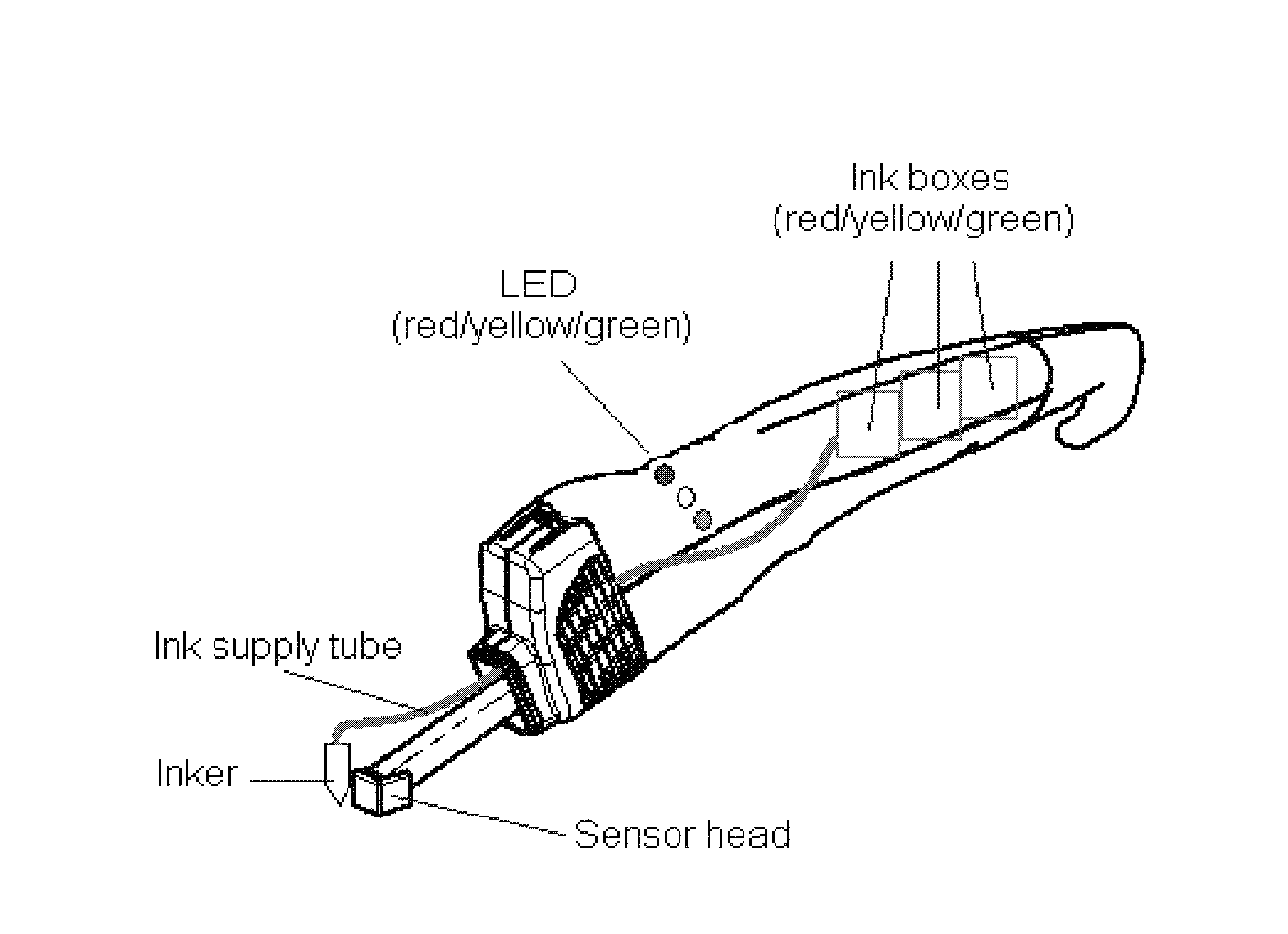
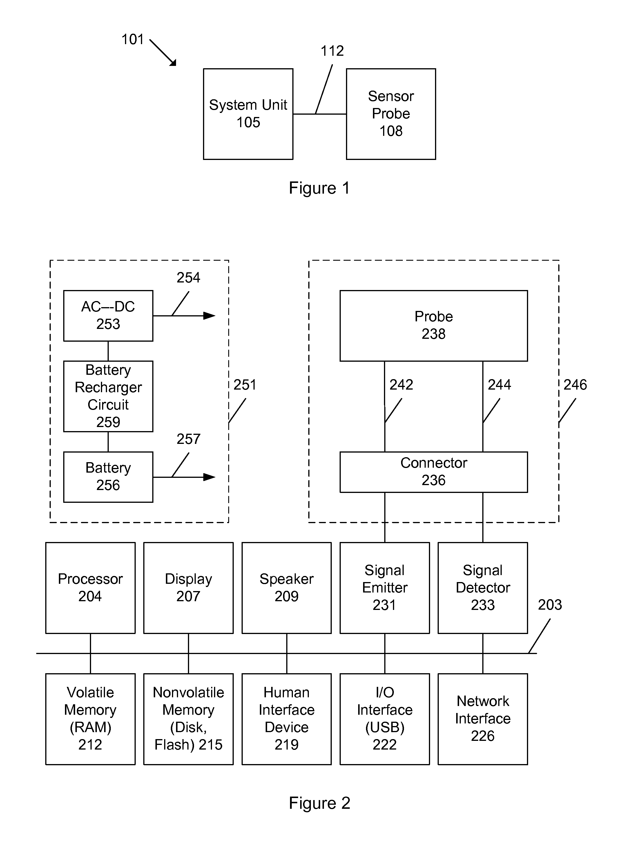
[0053]FIG. 1 shows an oximeter system 101 for measuring oxygen saturation of tissue in a patient. The system includes a system unit 105 and a sensor probe 108, which is connected to the system unit via a wired connection 112. Connection 112 may be an electrical, optical, or another wired connection including any number of wires (e.g., one, two, three, four, five, six, or more wires or optical fibers), or any combination of these or other types of connections. In other implementations of the invention, however, connection 112 may be wireless such as via a radio frequency (RF) or infrared communication.

[0054]Typically, the system is used by placing the sensor probe in contact or close proximity to tissue (e.g., skin or nerve) at a site where an oxygen saturation or other related measurement is desired. The system unit causes an input signal to be emitted by the sensor probe into the tissue (e.g., human tissue). There may be multiple input signals, and these signals may have varying or...


PUM


Abstract

A medical device such as an oximeter includes a marking feature. In an implementation, a marking mechanism of the device marks tissue based on a location of where a measurement was taken by the device. In an implementation, the marking mechanism of the device marks tissue based on an oxygen saturation measurement obtained by the device.

Description

BACKGROUND OF THE INVENTION[0001]The present invention relates to the field of medical devices, and more specifically to an oximeter or other medical device having a marking feature.[0002]Medical devices are among the marvels of modern medicine. Doctors and people use instruments to help diagnose and treat medical conditions and assist in medical and other procedures. Some revolutionary medical devices include the balloon catheter, oximeter, stent, and shunt. Over the years, these have improved the lives of many millions of people—allowing them to live better, longer, and more fulfilling lives.[0003]Medical devices continue to evolve and improve. Today's medical devices are more accurate, effective, and easier to use than those introduced just a few years ago. Many types of medical devices are even sold for people to use at home. Some common medical devices used by people at home are for monitoring blood pressure, blood glucose, fertility, body temperature (instantly and accurately)...

Claims


Application Information

Patent Timeline
Patent Type & Authority Patents(United States)
IPC IPC(8): A61B5/00
CPCA61B5/00A61B5/684A61B5/14551A61B2560/0431A61B5/742A61B90/39A61B2090/3908A61B2090/395A61B90/30A61B2090/308A61B2090/309A61B5/14552A61B5/7278A61B5/7282
Inventor HEATON, II, LARRY C.LASH, ROBERT E.
Owner VIOPTIX
Why Eureka
Try Eureka