Flow controller

a flow controller and flow rate technology, applied in process and machine control, pressure relieving devices on sealing faces, instruments, etc., can solve the problems of complex assembly operation, increased manufacturing cost, increased product size, etc., and achieve the effect of reducing power consumption, reducing the detection time of flow rate of fluid, and being small in scal

Active Publication Date: 2014-08-12
SMC CORP
View PDF33 Cites 17 Cited by
  • Summary
  • Abstract
  • Description
  • Claims
  • Application Information

AI Technical Summary

Benefits of technology

[0009]A general object of the present invention is to provide a flow controller, which can be made smaller in scale and simplified in structure, and which can reduce power consumption and be operated with low pressures when the flow rate of a fluid is controlled, together with enabling the flow rate to be controlled rapidly.
[0011]According to the present invention, by providing the flow rate detection unit including the detection unit, which is capable of detecting the flow rate of the fluid, in the body, which is equipped with the first and second passages and the throttling section through which the fluid flows, and by using the MEMS sensor in the detection unit, the detection time when the flow rate of the fluid is detected can be shortened, and the device can be made smaller in scale. Together therewith, since the device can be operated with low current, power consumption can be reduced. Further, because a balancing structure is provided for balancing a pressing force applied from the diaphragm assembly with respect to the valve body with a pressing force applied from the spring with respect to the valve body, the valve body can easily be operated by low-pressure pilot air. Together therewith, the spring can be set with a small elastic force, whereby the valve body can be operated rapidly and the flow rate control unit can be miniaturized, along with enabling the flow controller to be made smaller in scale.

Problems solved by technology

Furthermore, when the flow rate detector is assembled, since work is required to wind the heat-sensitive coils on the conduit and for welding the conduit with respect to the body, the assembly operation is complex, along with concerns over an increase in manufacturing costs.
As a result, there is a necessity for the return spring to be made large in scale, leading to a problem in that the product size is increased.
Further, in the case that the elastic force of the return spring is large, the minimum operating pressure must also be large, and thus there is a concern that the proportional valve cannot be operated at low pressures.
Further, for example, in the case that a solenoid valve, which is operated by a control signal, is disposed in the proportional valve in place of a diaphragm operated by air pressure, and a structure is provided therein for opening and closing the valve body by operating the solenoid valve, then power consumption is increased, and together therewith, cases can be expected in which accurate detection results cannot be obtained, as a result of heat generated at the solenoid section of the solenoid valve being transferred to the flow rate detector.

Method used


Image

  • Flow controller
  • Flow controller
  • Flow controller

Examples


Embodiment Construction

[0015]A preferred embodiment of a flow controller according to the present invention will be described below with reference to the accompanying drawings.

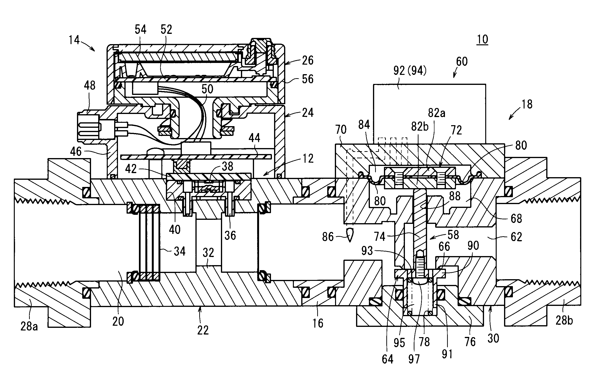
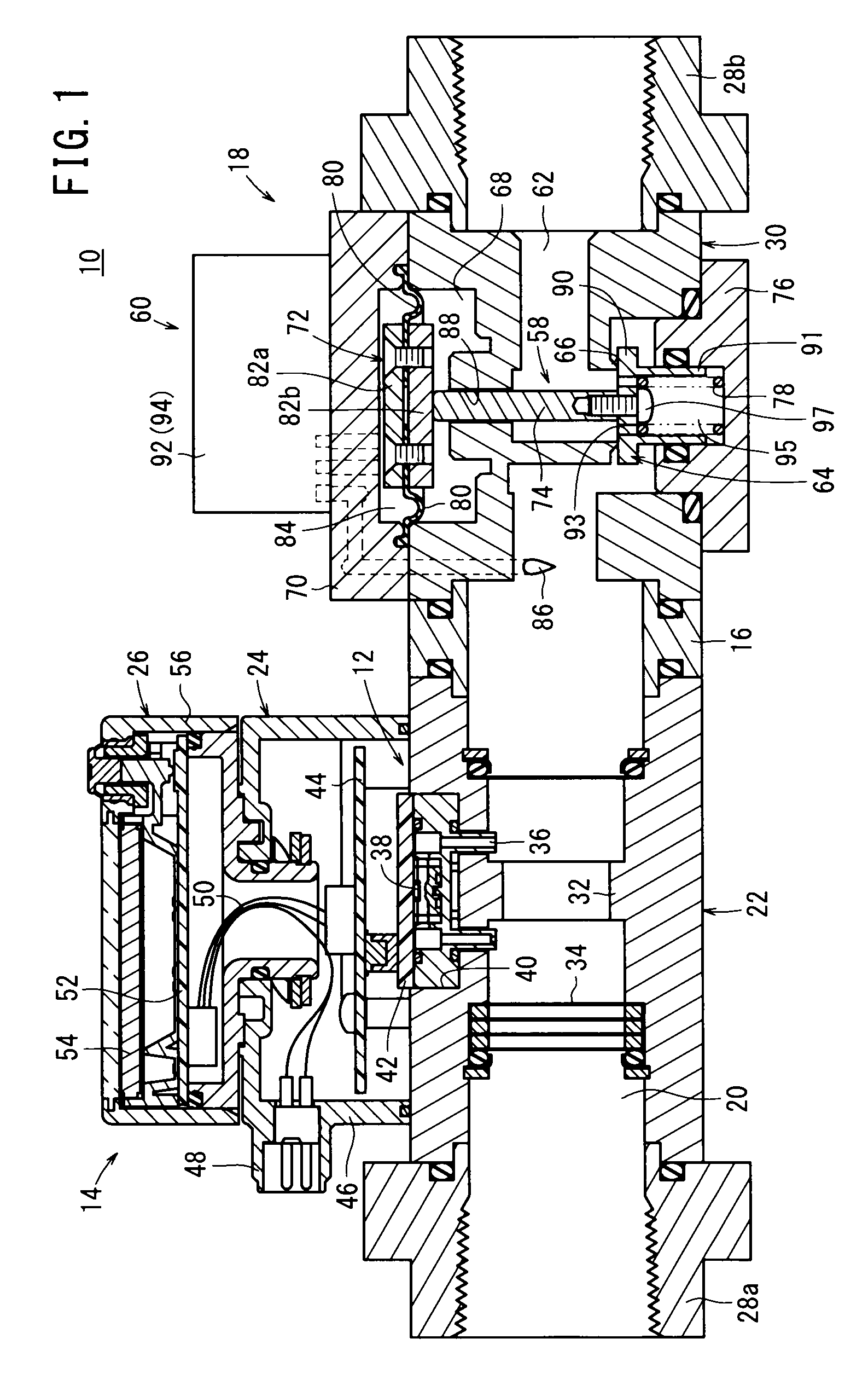
[0016]In FIG. 1, reference numeral 10 indicates a flow controller according to an embodiment of the present invention.

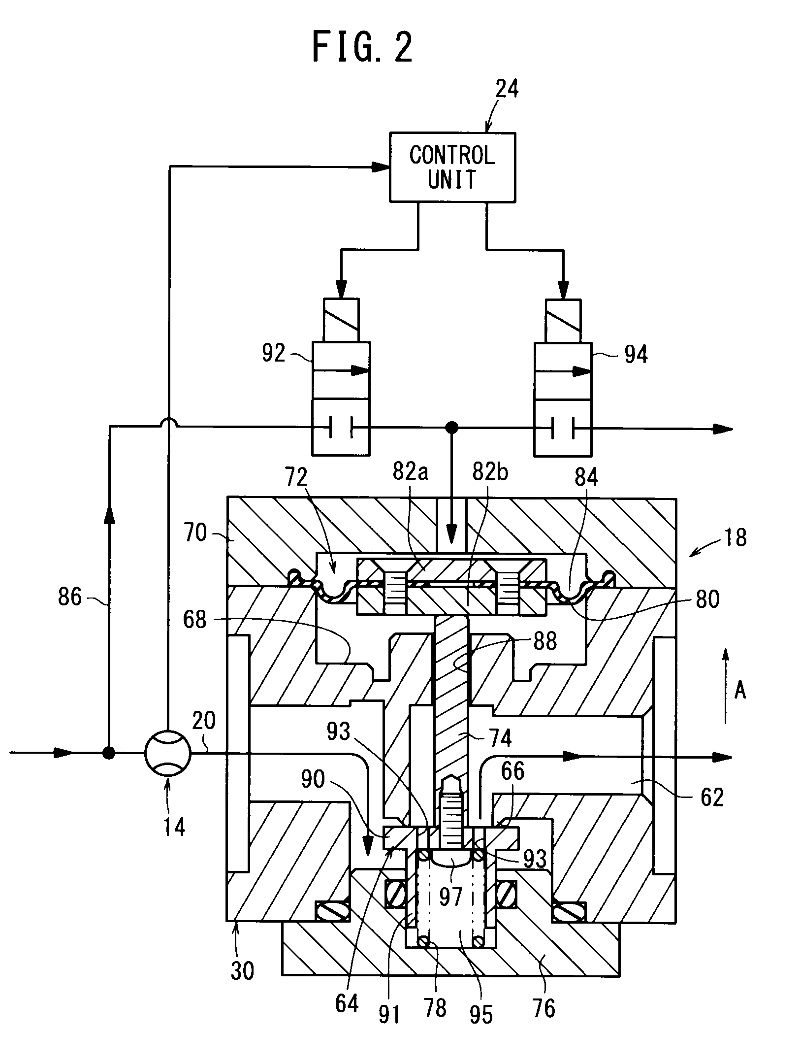
[0017]As shown in FIGS. 1 through 3, the flow controller 10 includes a flow rate detection unit (flow rate detector) 14 equipped with a detection unit 12 for detecting a flow rate of a fluid, and a flow rate control unit (flow rate controller) 18 connected through an adapter 16 to the flow rate detection unit 14 and which is capable of adjusting the flow rate of the fluid. A fluid (e.g., air), which is supplied from a non-illustrated fluid supply source, after having been supplied from the side of the flow rate detection unit 14, flows to the flow rate control unit 18. Further, the flow rate detection unit 14 and the flow rate control unit 18 may be connected to each other directly, without intervention of the aforem...


PUM


Abstract

A flow controller includes a flow detection unit that includes a detection unit for detecting the flow rate of a fluid; and a flow control unit that is coupled to the flow detection unit and that is capable of adjusting the flow rate of the fluid. The detection sensor constituting the detection unit includes a thermal flow sensor using MEMS technology, and the flow rate of the fluid that has been detected by the detection sensor is output to a control unit. In addition, in the flow control unit, the supply state of air to a supply room is switched by each of a supply-use solenoid valve and an exhaust-use solenoid valve, and on the basis of the supply state of the air, a control valve opens and closes.

Description

TECHNICAL FIELD[0001]The present invention relates to a flow controller, which is capable of detecting the flow rate of a fluid that flows through a passage and of controlling the flow rate.BACKGROUND ART[0002]Heretofore, as disclosed in the specification of Japanese Patent No. 2784154, a flow controller is constituted from a flow rate detector for measuring the flow rate of a fluid, and a proportional valve disposed in parallel with the flow rate detector. A main flow passage extends through the interior of the flow rate detector. On the inner wall of the main flow passage, a conduit inlet and a conduit outlet are opened, which are connected respectively to a conduit. A pair of heat-sensitive coils are wound on the conduit, which are connected to an amplifier. In addition, the flow rate of the fluid that flows through the conduit is estimated using a difference in resistance, which occurs due to a temperature difference generated between the heat-sensitive coils.[0003]Further, in t...

Claims


Application Information

Patent Timeline
Patent Type & Authority Patents(United States)
IPC IPC(8): F16K31/02
CPCY10T137/777G01F1/684G05D7/03Y10T137/87209G05D7/0629Y10T137/7759G01F5/00Y10T137/7768Y10T137/7761G05D7/005G01F1/00G05D7/06
Inventor SAKASEGAWA, TAKESHIOSHIMA, YUTA
Owner SMC CORP
Why Eureka
Try Eureka