Envelope tracking system for MIMO

a tracking system and envelope technology, applied in the field of amplifiers, can solve the problems of increasing the overhead associated with the mimo transmitter, and achieve the effect of minimising distortion

Active Publication Date: 2014-08-12
SNAPTRACK
View PDF16 Cites 72 Cited by
  • Summary
  • Abstract
  • Description
  • Claims
  • Application Information

AI Technical Summary

Problems solved by technology

Whilst the use of an envelope tracking modulated power supply provides an efficient amplification arrangement, it increases the overhead associated with the MIMO transmitter since an envelope tracking modulator stage is required for each power amplifier of the MIMO system.

Method used


Image

  • Envelope tracking system for MIMO
  • Envelope tracking system for MIMO
  • Envelope tracking system for MIMO

Examples


Embodiment Construction

[0026]The invention will now be described with further reference to the exemplary RF amplification architecture of a MIMO transmitter system of a mobile communication system. Whilst the invention and its embodiments may be advantageously utilised in such an environment, the invention and its embodiments are not limited in their applicability to the exemplary architectures and implementations as illustrated.

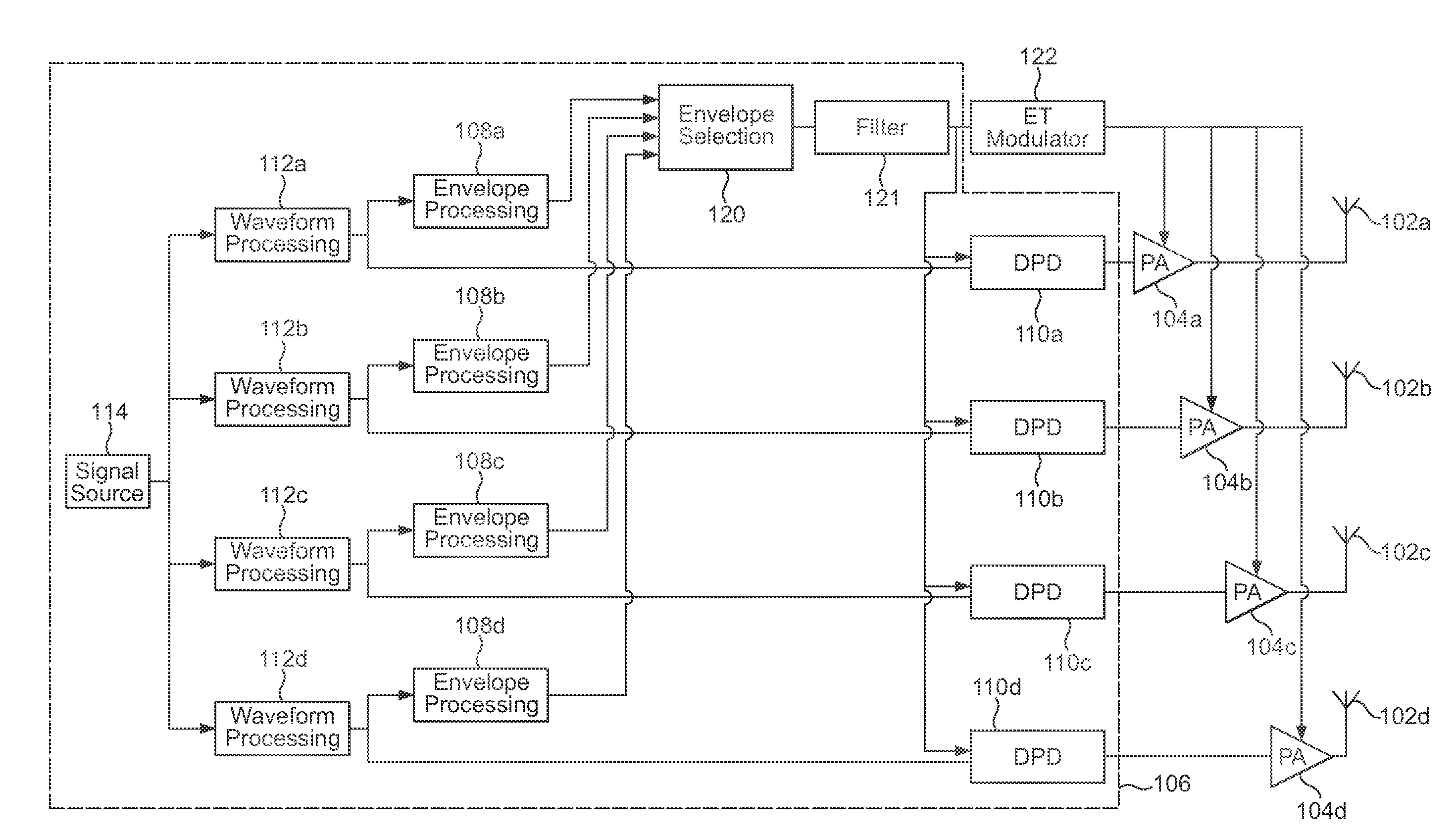
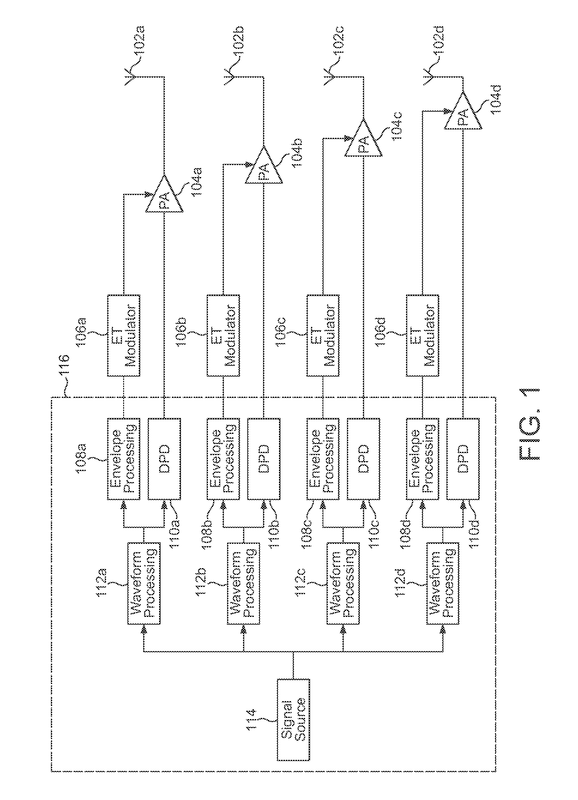
[0027]With reference to FIG. 1 there is illustrated an implementation of conventional envelope tracking techniques in a MIMO transmitter.

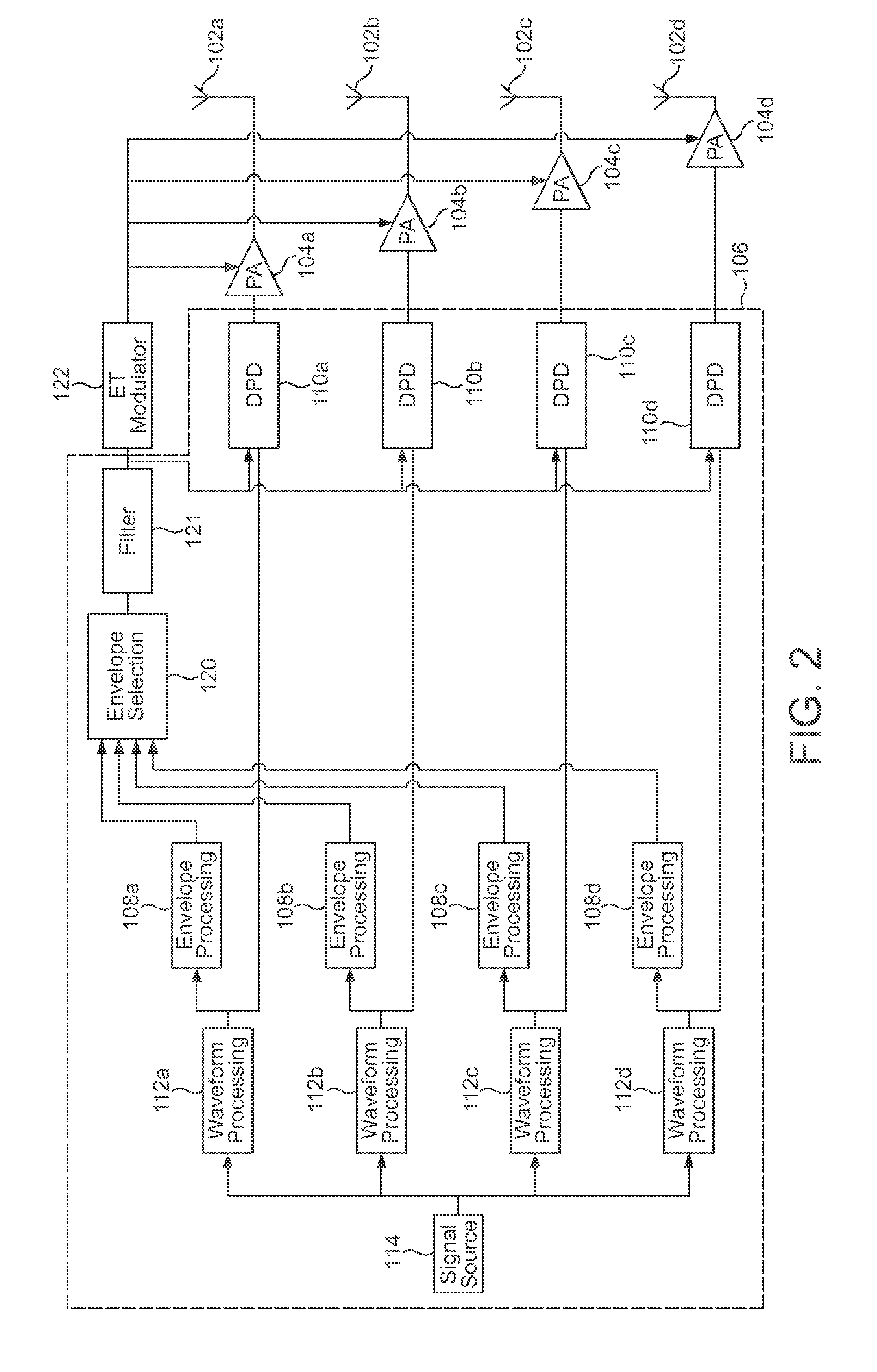
[0028]The MIMO transmitter includes a digital signal processing block including a signal source 114, a plurality of waveform processing blocks 112a to 112d, a plurality of envelope processing blocks 108a to 108d, and a plurality of digital pre-distortion blocks 110a to 110d; a plurality of envelope modulators 106a to 106d; a plurality of RF amplifiers 104a to 104d; and a plurality of antennas 102a to 102d.

[0029]The signal source 114 may generate...


PUM


Abstract

There is disclosed an amplifier arrangement comprising a plurality of amplifiers each arranged to amplify one of a plurality of different input signals, the arrangement comprising an envelope tracking modulator for generating a common power supply voltage for the power amplifiers, and further comprising an envelope selector adapted to receive a plurality of signals representing the envelopes of the plurality of input signals, and adapted to generate an output envelope signal representing the one of the plurality of envelopes having the highest level at a particular time instant as the input signal for the envelope tracking modulator.

Description

CROSS-REFERENCE TO RELATED APPLICATIONS[0001]Patent application GB 1110732.3, filed Jun. 24, 2011, is incorporated herein by reference.BACKGROUND TO THE INVENTION[0002]1. Field of the Invention[0003]The present invention relates to an amplification stage incorporating multiple power amplifiers having different input signals. The invention is particularly but not exclusively concerned with multiple power amplifiers in a transmitter of a MIMO system, for example in a cellular infrastructure base station or micro base station of a mobile communication system.[0004]2. Description of the Related Art[0005]MIMO (multiple input, multiple output) systems are well known in the field of mobile telecommunications. A MIMO transmitter generates multiple waveforms from a single signal source, which are amplified by multiple power amplifiers to provide multiple signal paths. The transmitted signals on the multiple paths are detected at one or more receivers.[0006]It is well known in the art of RF p...

Claims


Application Information

Patent Timeline
Patent Type & Authority Patents(United States)
IPC IPC(8): H03F3/68
CPCH04L27/367H03F2200/321H03F2200/504H04W52/52H03F1/0222H03F2201/3215H03F3/602H04B7/0413H03F1/3247H03F3/68H03F2201/3227H03F3/19H03F2200/102H04B7/06H03F2200/451H03F3/211H03F2203/21181H03F3/24H03F3/245H03F1/02H03F2203/21106H04B1/0475H04B7/0417H04B2001/0425
Inventor WIMPENNY, GERARD
Owner SNAPTRACK
Why Eureka
Try Eureka