
Liquid crystal display

a liquid crystal display and liquid crystal technology, applied in the field of liquid crystal displays, can solve the problems of reducing the yield reducing the luminance of the liquid crystal display, and reducing the quality of the display, so as to avoid the effect of unnecessary capacitive coupling, reducing the luminance deterioration of the liquid crystal display, and avoiding display quality degradation

Active Publication Date: 2014-08-12
SAMSUNG DISPLAY CO LTD
View PDF32 Cites 2 Cited by
  • Summary
  • Abstract
  • Description
  • Claims
  • Application Information

AI Technical Summary

Benefits of technology

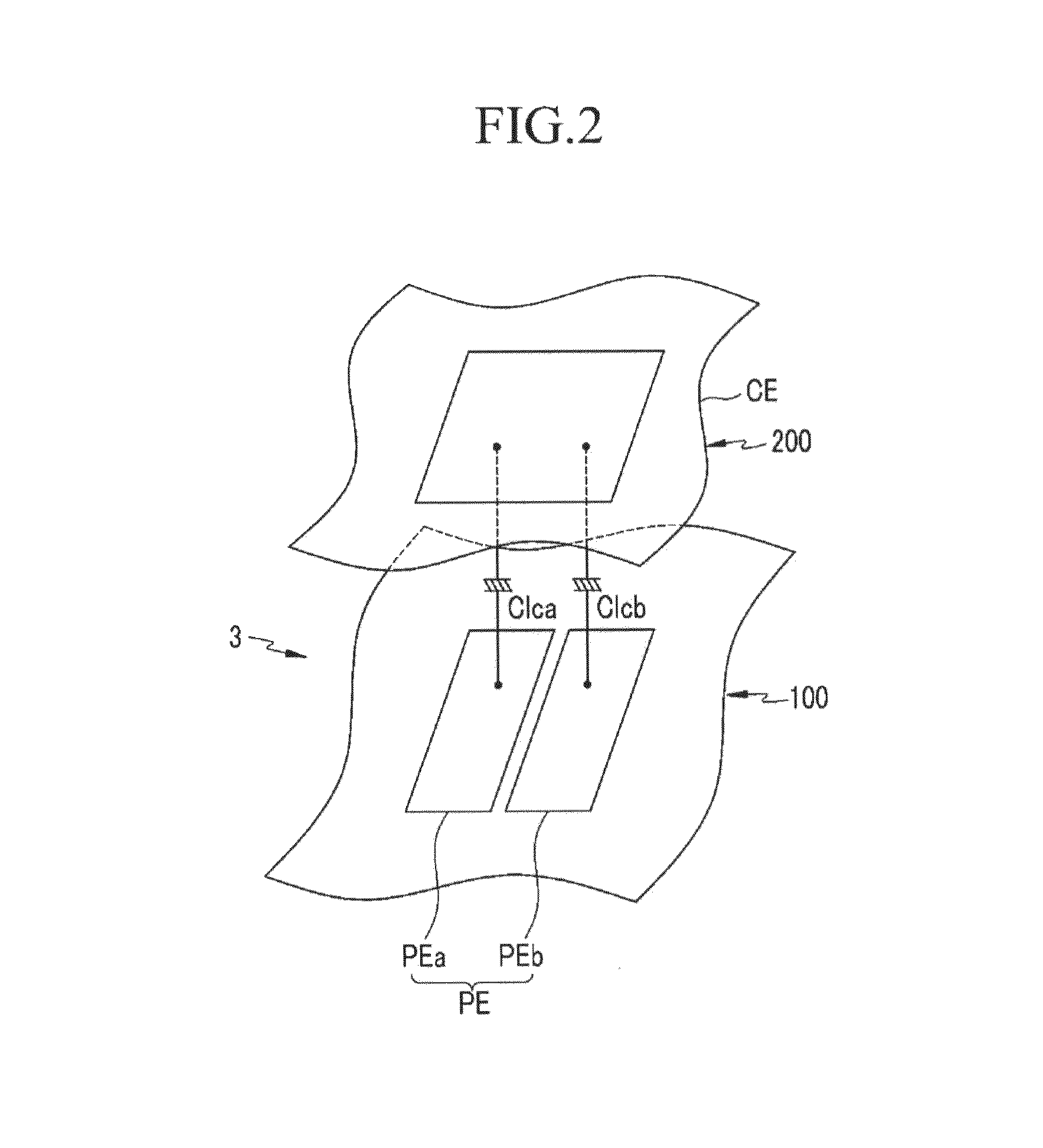
[0010]The present invention prevents or reduces capacitive coupling between a data line and a common electrode, to prevent reduction in display quality of a liquid crystal display, to reduce deterioration of luminance of the liquid crystal display, and to improve process yield.
[0020]According to an exemplary embodiment of the present invention, without the shielding electrode, unnecessary capacitive coupling between the data line and the common electrode may be prevented and display quality deterioration may be avoided. Also, luminance deterioration of the liquid crystal display may be reduced and process yield may be increased.

Problems solved by technology

However, in this driving method, a charging capacitance charged to the liquid crystal layer for each pixel column is altered by unnecessary coupling between a voltage applied to a data line and a voltage applied to a common electrode, such that display quality may be decreased.
However, when using this shielding electrode, luminance of the liquid crystal display is reduced and a short between the shielding electrode and the data line may be generated, reducing yield of the liquid crystal display.

Method used


Image

  • Liquid crystal display
  • Liquid crystal display
  • Liquid crystal display

Examples


case 1

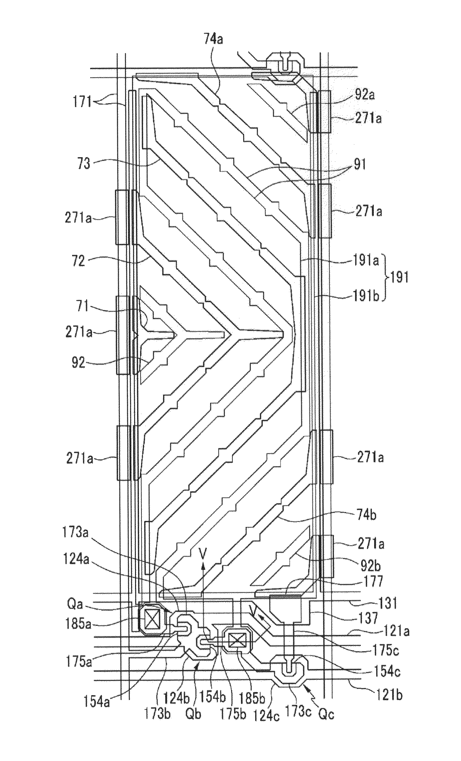
[0111]In case 1, the interval between the edge of the data line 171 and the edge of the opening 271a of the common electrode is about 3 μm. In case 2, the corresponding interval is about 5 μm.

[0112]

TABLE 1Case 1Case 2A98%98%B83%77%

[0113]Referring to Table 1 and case 1, when an opening 271a is present in the common electrode, the magnitude of the voltage applied to the common electrode is maintained at about 98% of the voltage magnitude present in a conventional liquid crystal display with a shielding electrode, confirming that the change in voltage due to the opening 271a is small. Also, the magnitude of the electric field between the data line and the common electrode is decreased to about 83% and about 77% of the magnitude present in a conventional display with a shielding electrode.

[0114]In summary, when employing a configuration of the present invention, the magnitude of the electric field between the data line and the common electrode is decreased by more than 20%, without subs...


PUM

PropertyMeasurementUnit
distanceaaaaaaaaaa
voltageaaaaaaaaaa
green coloraaaaaaaaaa

Abstract

In a liquid crystal display according to an exemplary embodiment of the present invention, a shielding electrode applied with the same voltage as a common voltage and overlapping a data line is not formed. Instead, an opening is formed at a position corresponding to a data line disposed proximate to a sub-pixel charged with a relatively low voltage. In this manner, luminance deterioration of a liquid crystal display may be reduced or prevented, and a short defect between the shielding electrode and the data line may also be prevented.

Description

CROSS-REFERENCE TO RELATED APPLICATION[0001]This application claims priority to, and the benefit of, Korean Patent Application No. 10-2011-0032590 filed in the Korean Intellectual Property Office on Apr. 8, 2011, the entire contents of which are incorporated herein by reference.BACKGROUND OF THE INVENTION[0002](a) Field of the Invention[0003]Embodiments of the present invention relate generally to liquid crystal displays. More specifically, embodiments of the present invention relate to liquid crystal displays having reduced parasitic capacitance.[0004](b) Description of the Related Art[0005]A liquid crystal display is currently one of the most widely used types of flat panel displays. The typical liquid crystal display includes two display panels on which field generating electrodes such as a pixel electrode and a common electrode are formed, and a liquid crystal layer that is disposed therebetween. An image is displayed by applying a voltage to a field generating electrode to gene...

Claims


Application Information

Patent Timeline
Patent Type & Authority Patents(United States)
IPC IPC(8): G02F1/1343G02F1/136
CPCG02F1/134309G02F2001/134318G02F1/134318G02F1/133G02F1/1343G02F1/13624G02F1/1368
Inventor LEE, SEONG YOUNGCHOI, JAE-HO
Owner SAMSUNG DISPLAY CO LTD
Learn More