
Magnetic resonance imaging device and control method thereof

a magnetic resonance imaging and control method technology, applied in the field of magnetic resonance imaging, can solve the problems of tedious feeling and degrading the quality of the obtained magnetic resonance imaging images, and achieve the effect of lessening the tedium experienced by the patient and preventing the patient from moving

Inactive Publication Date: 2014-08-12
SAMSUNG ELECTRONICS CO LTD
View PDF6 Cites 5 Cited by
  • Summary
  • Abstract
  • Description
  • Claims
  • Application Information

AI Technical Summary

Benefits of technology

The patent describes a magnetic resonance imaging device that has a monitor inside to show photos and images to the patient. This helps to make the diagnosis process less boring for the patient and stops them from moving during the process.

Problems solved by technology

Longer photographic time typically makes the patient feel tedious, and if the patient moves during the photographing time to adjust to the tedium, the quality of the obtained MRI images is degraded.

Method used


Image

  • Magnetic resonance imaging device and control method thereof
  • Magnetic resonance imaging device and control method thereof
  • Magnetic resonance imaging device and control method thereof

Examples


Embodiment Construction

[0040]Reference will now be made in detail to preferred embodiments of the present invention, examples of which are illustrated in the accompanying drawings, wherein like reference numerals refer to like elements throughout. This invention may, however, be embodied in many different forms and should not be construed as limited to the exemplary embodiments set forth herein. In the following description, a detailed explanation of known related functions and constructions may be omitted to avoid unnecessarily obscuring the subject matter of the present invention. Also, terms described herein, which are defined considering the functions of the present invention, may be implemented differently depending on user and operator's intention and practice. Therefore, the terms should be understood on the basis of the disclosure throughout the specification. The principles and features of this invention may be employed in varied and numerous embodiments without departing from the scope of the in...


PUM


Abstract

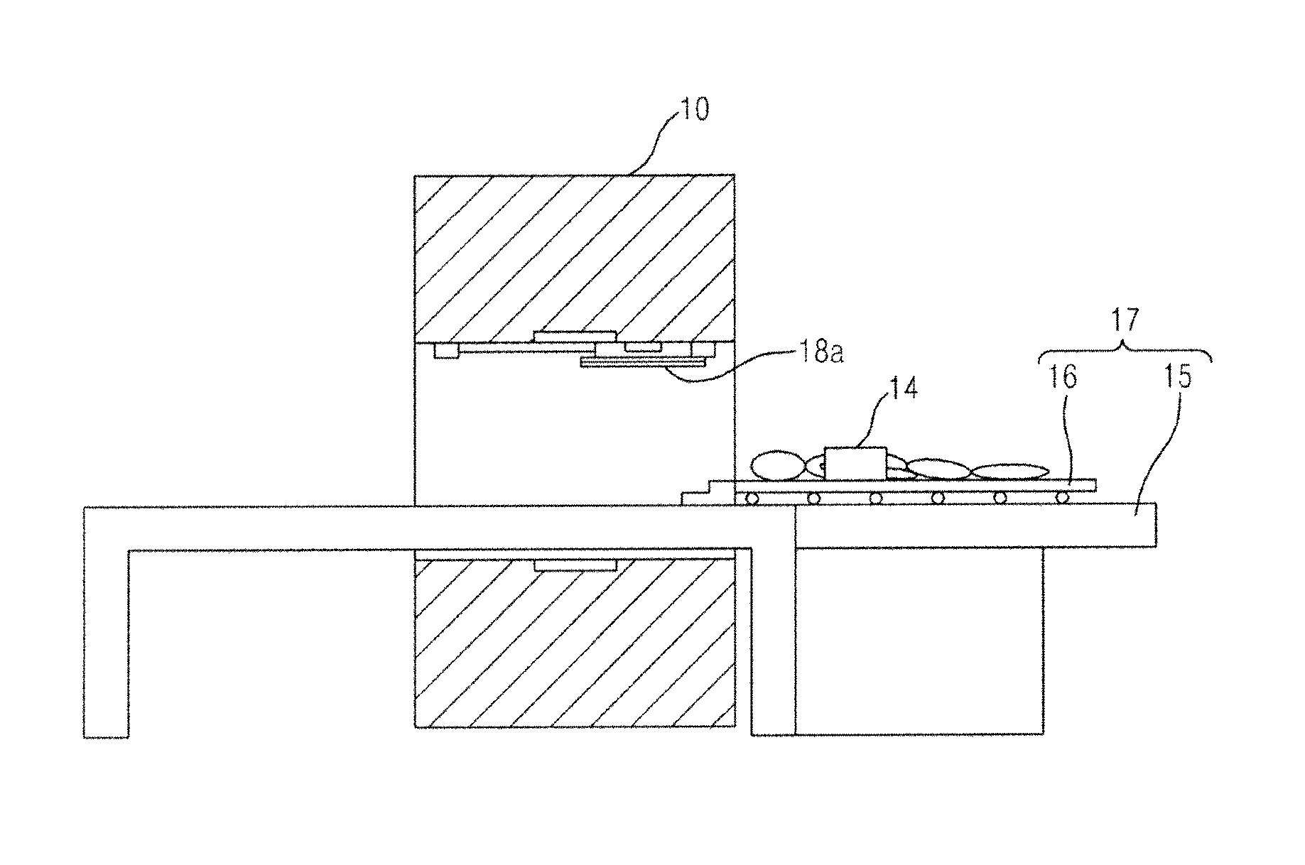
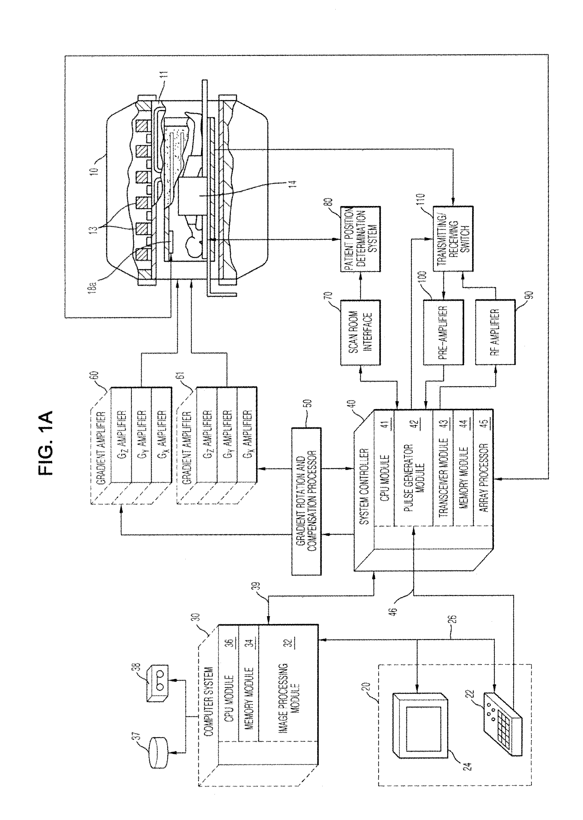
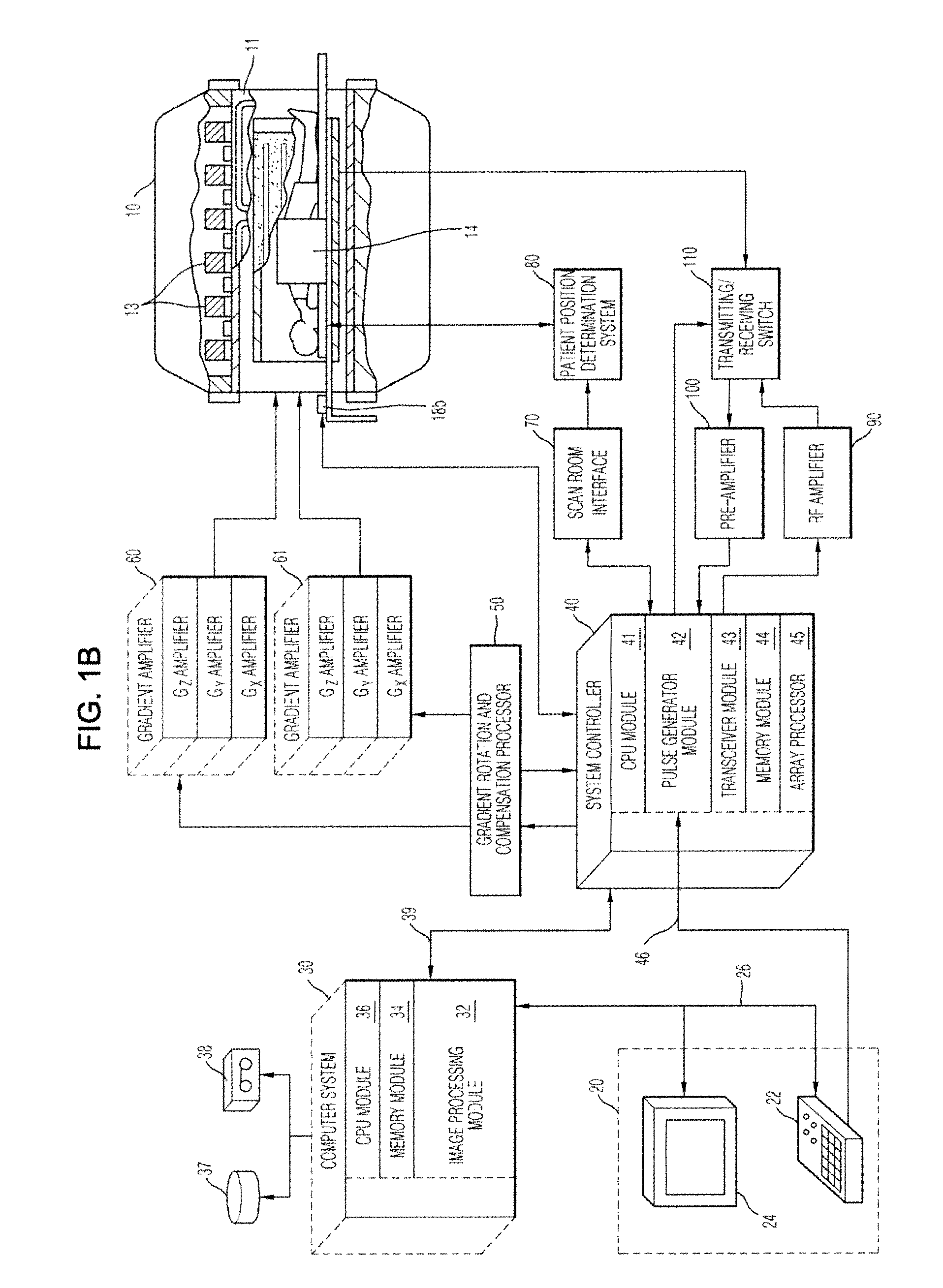
A magnetic resonance imaging device and a control thereof, with the magnetic resonance imaging device including a magnet assembly, a patient table provided with a transfer unit introducing a patient to inside of the magnet assembly and a fixing unit supporting the transfer unit, an image output unit which is provided on the magnet assembly or the patient table to output photographic information or general image information of the magnetic resonance imaging device, and a system control unit configured to perform control such that an image of the image output device is output over a facial area of a patient positioned in the magnet assembly according to a moving distance of the transfer unit and thus the patient sees the photographic information or the general image information in the magnet assembly, thereby providing the patient with photographic information.

Description

CLAIM OF PRIORITY[0001]This application claims, pursuant to 35 U.S.C. §119(a), priority to and the benefit of the earlier filing date of a Korean Patent Application No. 2011-0090975, filed on Sep. 8, 2011 in the Korean Intellectual Property Office, the disclosure of which is incorporated herein by reference.BACKGROUND OF THE INVENTION[0002]1. Field of the Invention[0003]The present invention relates to magnetic resonance imaging, and in particular to a magnetic resonance imaging device used to diagnose various diseases by use of a magnetic resonance image and a control method thereof.[0004]2. Description of the Related Art[0005]In general, a medical imaging device provides an image obtained from a patient. The medical imaging device may include ultrasonic diagnostic equipment, x-ray tomography equipment, magnetic resonance imaging equipment, and medical diagnostic equipment. Typically, magnetic resonance imaging equipment functions under relatively less stringent conditions for phot...

Claims


Application Information

Patent Timeline
Patent Type & Authority Patents(United States)
IPC IPC(8): A61B5/055
CPCA61B5/0033G01R33/283A61B5/055
Inventor YANG, WHOE, SUN
Owner SAMSUNG ELECTRONICS CO LTD
Learn More