Gradient AOCV methodology enabling graph-based timing closure with AOCV timing models

a graph-based timing and graph-based technology, applied in the field of timing closure, can solve the problems of difficult to meet frequency goals, limited accuracy of timing analysis using typically, and down the cell, so as to improve correlation, reduce pessimism, and accurate delay estimation

Active Publication Date: 2014-08-12
TEXAS INSTR INC
View PDF11 Cites 8 Cited by
  • Summary
  • Abstract
  • Description
  • Claims
  • Application Information

AI Technical Summary

Benefits of technology

[0019]This invention uses a modified / custom Advanced On Chip Variation (AOCV) Tables based on design depth profile derived from standard AOCV tables provided by a library team. This invention enables direct use of AOCV tables modified for optimization. There is no need of layout tool to signoff tool iterations to identify instance / cell based derates. There is no need for any flat derates to be applied. Cells still have multiple derates possible versus constant derate in case of cell / instance based solution enabling accurate delay estimation for paths with various depth.
[0020]This invention provides AOCV Comprehension during all stages of layout optimization. This invention reduces pessimism with Graph based AOCV Timer numbers. This invention provides improved Correlation between Path based timing numbers versus Graph based timing numbers. This invention enables near Path Based Analysis (PBA) AOCV timing closure using Electronic Design Automation (EDA) tools capable of only doing GBA AOCV timer update. This invention improves crosstalk modeling. This invention removes many false window overlappings. This invention reduces area / power used due to G AOCV pessimism reduction. This invention provides improved TAT. This invention reduces ECO cycles as layout timing is well correlated to signoff.

Problems solved by technology

The accuracy of the timing analysis is limited using the typically employed graph based analysis method.
Thus the derate slows down the cell and makes it harder to meet the frequency goals.
Thus GBA analysis may be extremely pessimistic and lead to waste of time and resources solving the wrong problem.

Method used


Image

  • Gradient AOCV methodology enabling graph-based timing closure with AOCV timing models
  • Gradient AOCV methodology enabling graph-based timing closure with AOCV timing models
  • Gradient AOCV methodology enabling graph-based timing closure with AOCV timing models

Examples


Embodiment Construction

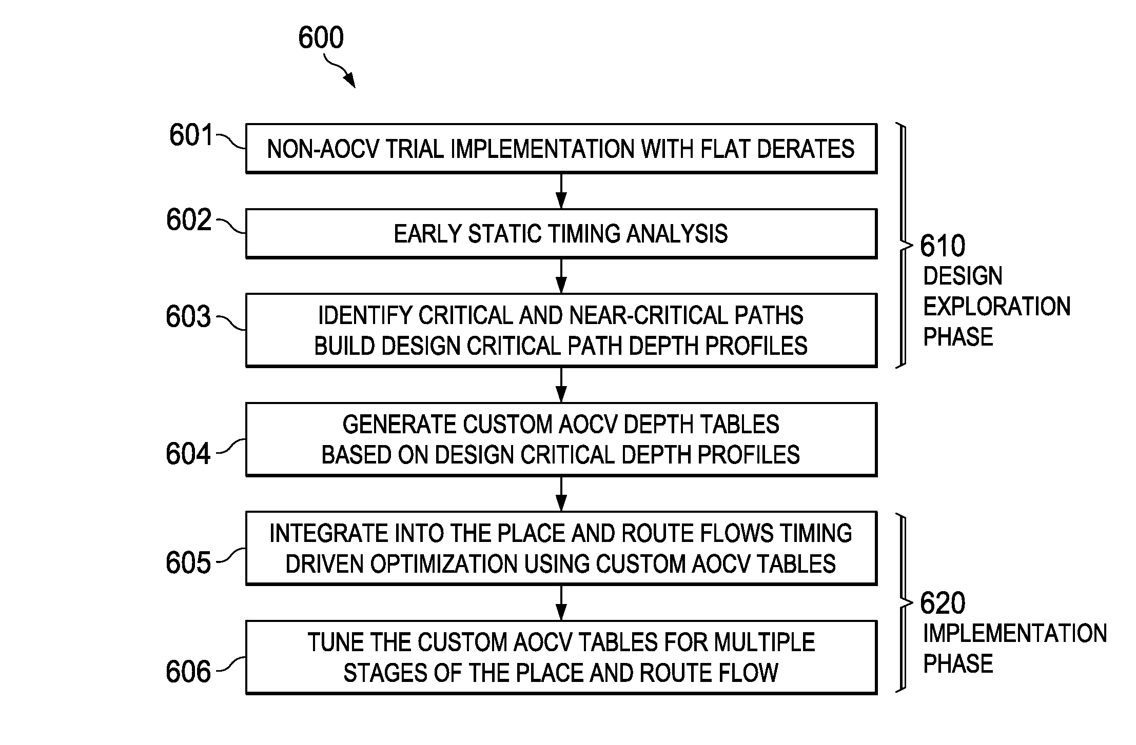
[0029]This invention concerns timing closure in integrated circuit design. Timing closure means that the circuit of the integrated circuit preforms its intended function in a timely manner to feed other subsequent functions.

[0030]A technique called variation comprehension in layout optimization is often used for effective timing closure and to reduce signoff-timer to layout iterations. A typical prior art technique uses flat derate based closure which employs very pessimistic assumptions for safety. These pessimistic assumptions result in increased area and power requirements than are necessary. These pessimistic assumptions may result in some designs that cannot be closed. This means that the designed circuit cannot be assured of operating correctly at the intended speed. Thus it is not practical to derive a single flat derate covering whole library

[0031]The prior art includes the following techniques to attempt to solve this problem. The first such technique is custom cell based d...


PUM


Abstract

A method of manufacturing semiconductor circuits seeks timing closure on a preliminarily select, placed and routed set of cells using a delay for each cell as derated by a derate value obtained from a timing model table having a derate value corresponding to a circuit path depth in the netlist. The derate value for a predetermined number of circuit path depths below k are identical. The derate values are monotonically decreasing for increasing circuit depths in a range between 1.0 and 1.5. Separate timing model tables with differing identical values can be employed for standard and clock tree cells.

Description

CLAIM OF PRIORITY[0001]This application claims priority under 35 U.S.C. 119(e)(1) to U.S. Provisional Application No. 61 / 702,044 filed Sep. 17, 2012.TECHNICAL FIELD OF THE INVENTION[0002]The technical field of this invention is timing closure in integrated circuit design.BACKGROUND OF THE INVENTION[0003]This invention related to Graph Based Analysis (GBA) Advanced On Chip Variation (AOCV) Timing Correlation to Path Based Analysis (PBA) Timing and AOCV Comprehension during layout optimization. This invention reduces GBA AOCV Timing Pessimism and improves Performance, Power-Active, Power-Leakage and Area (PPPA) performance.[0004]Synchronous digital circuits are designed for operation at specific clock frequencies. The goals of synthesis and place and route (PnR) optimizations is to realize this frequency of operation in real design layout. Timing closure is the effort expended towards meeting the frequency of operation goals of the design / circuit during the layout. Timing closure invo...

Claims


Application Information

Patent Timeline
Patent Type & Authority Patents(United States)
IPC IPC(8): G06F17/50
CPCG06F17/5081G06F17/5031G06F2217/84G06F30/3312G06F30/398G06F2119/12
Inventor SHAIKH, RAASHID MOINRAJAN, VISHNURAJ ARUKAT
Owner TEXAS INSTR INC
Why Eureka
Try Eureka