System and method for pixelated detector calibration

a detector and calibration system technology, applied in the field of system and method for pixelated detector calibration, can solve problems such as difficulties in reconstructing an image of a 3d object (e.g., a patient tissu

Active Publication Date: 2014-08-19
GENERAL ELECTRIC CO
View PDF28 Cites 13 Cited by
  • Summary
  • Abstract
  • Description
  • Claims
  • Application Information

AI Technical Summary

Problems solved by technology

One challenge in the use of such configurations is that the light yield across different scintillators may vary, and the operating parameters of the pixelated detectors may also vary.
These differences and variations may result in difficulties in reconstructing an image of a 3D object (e.g., a patient tissue).

Method used


Image

  • System and method for pixelated detector calibration
  • System and method for pixelated detector calibration
  • System and method for pixelated detector calibration

Examples


Embodiment Construction

[0022]One or more specific embodiments will be described below. In an effort to provide a concise description of these embodiments, all features of an actual implementation may not be described in the specification. It should be appreciated that in the development of any such actual implementation, as in any engineering or design project, numerous implementation-specific decisions must be made to achieve the developers' specific goals, such as compliance with system-related and business-related constraints, which may vary from one implementation to another. Moreover, it should be appreciated that such a development effort might be complex and time consuming, but would nevertheless be a routine undertaking of design, fabrication, and manufacture for those of ordinary skill having the benefit of this disclosure.

[0023]When introducing elements of various embodiments of the present invention, the articles “a,”“an,”“the,” and “said” are intended to mean that there are one or more of the ...


PUM


Abstract

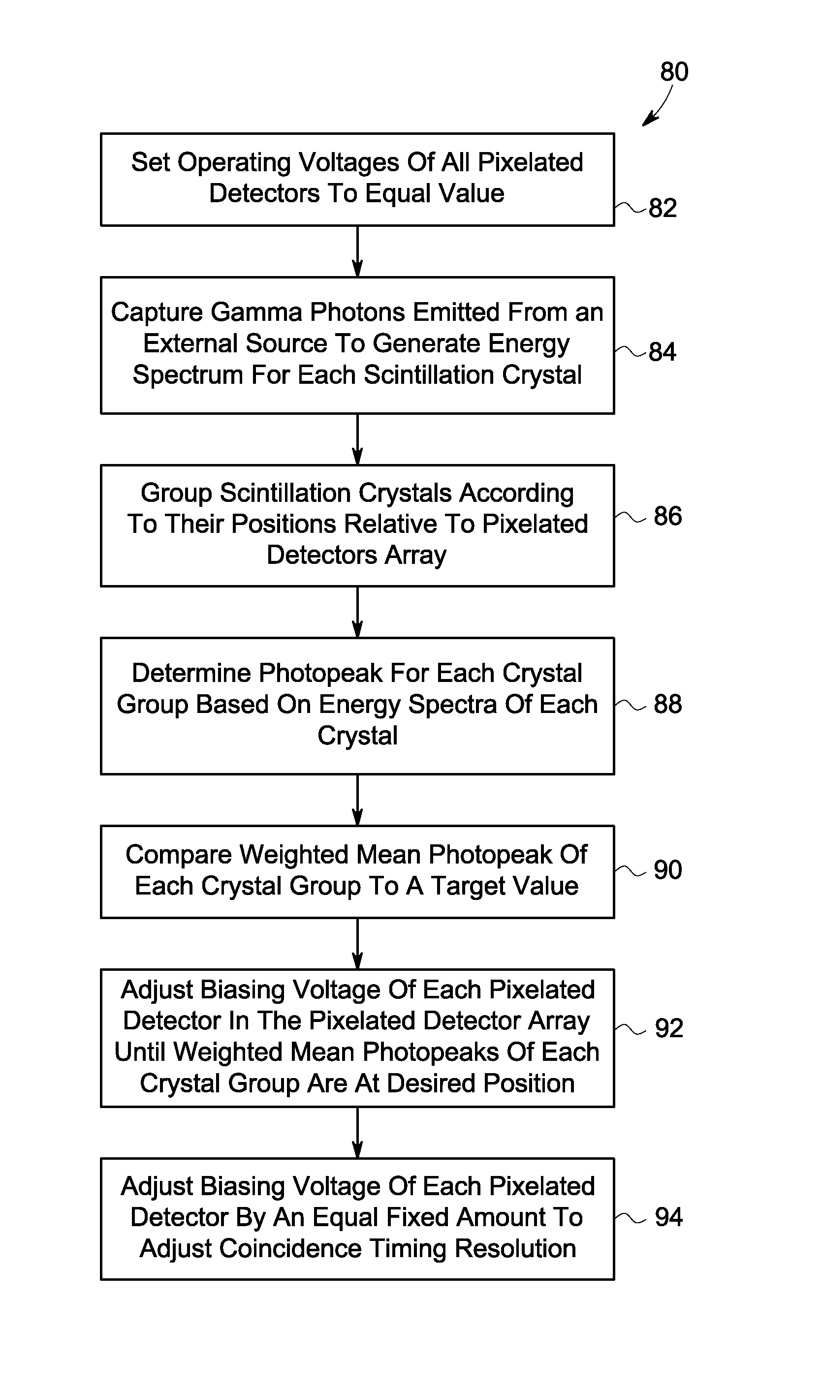
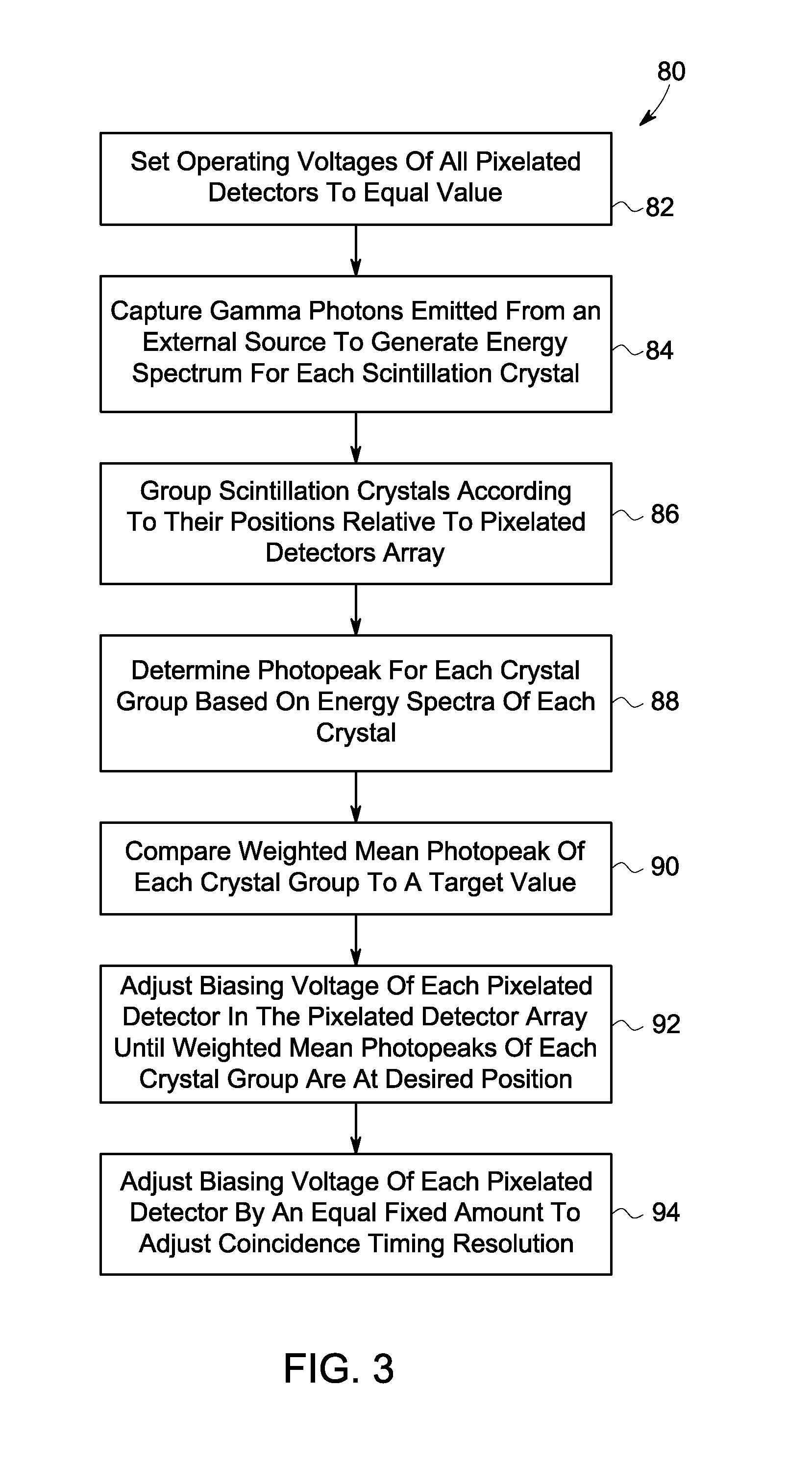
Present embodiments relate to the calibration of detectors having one or more arrays of pixelated detectors. According to an embodiment, a method includes detecting optical outputs generated by a plurality of scintillation crystals of a detector with an array of pixelated detectors, generating, with the array of pixelated detectors, respective signals indicative of the optical outputs, generating, from the respective signals, a unique energy spectrum correlated to each of the plurality of scintillation crystals, grouping subsets of the plurality of scintillation crystals into macrocrystals, determining a representative energy spectrum peak for each macrocrystal based on the respective energy spectra of the scintillation crystals in the macrocrystal, comparing a value of the representative energy spectrum peak for each macrocrystal with a target peak value, and adjusting an operating parameter of at least one pixelated detector in the array of pixelated detectors as a result of the comparison.

Description

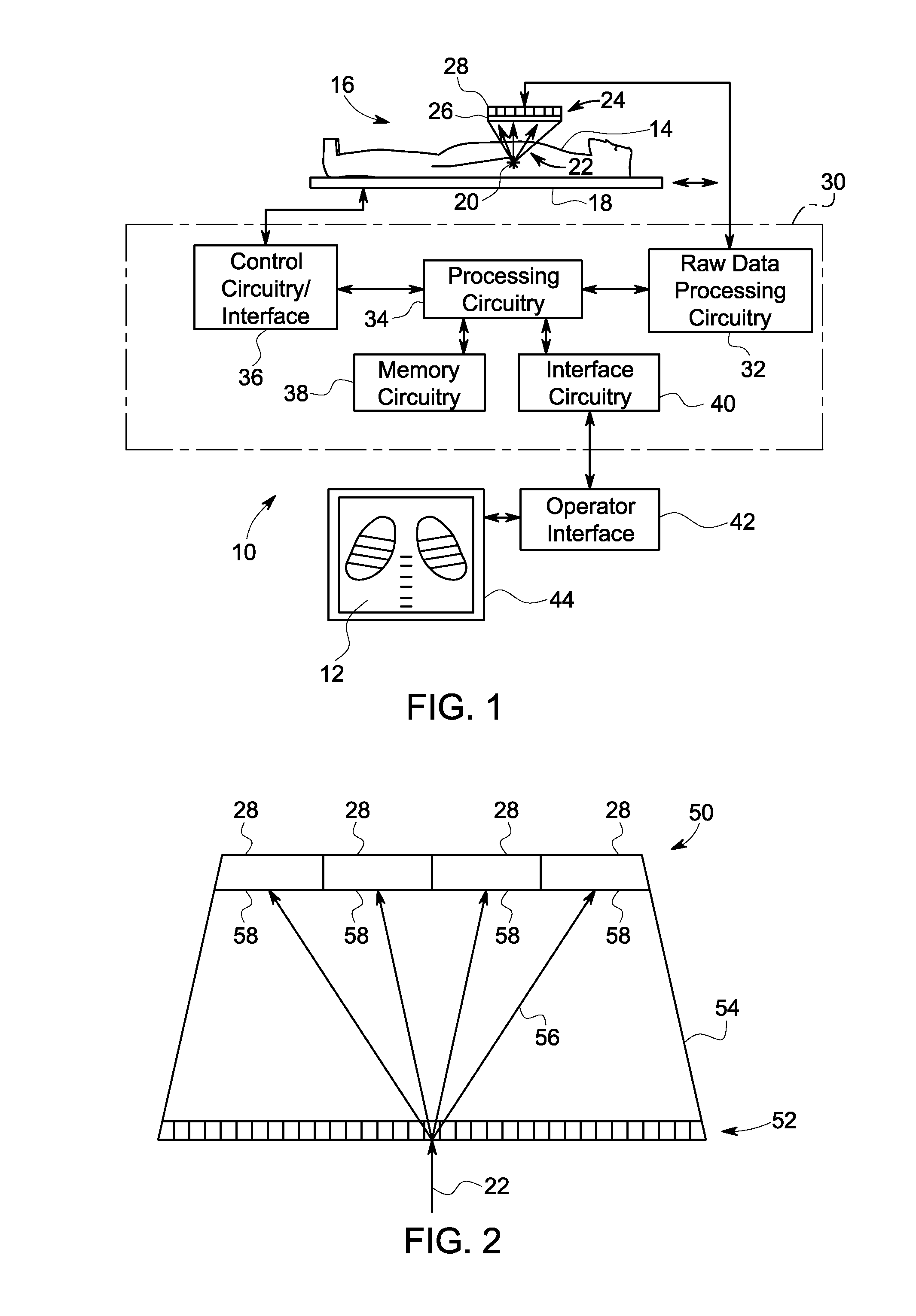
BACKGROUND[0001]A wide range of imaging techniques are known and currently in use, particularly for medical diagnostic applications. Certain of these techniques, commonly referred to as nuclear imaging, rely on the detection of gamma rays during the radioactive decay of a radioisotope (or radionuclide), commonly administered in the form of a radiopharmaceutical agent that can be carried, and in some cases, bound to particular tissues of interest. A gamma ray detector detects the emissions via a gamma camera that typically includes a collimator, a scintillator, an array of pixelated photodetectors (such as photomultiplier tubes, avalanche photodiodes etc.) with individual gain adjustment capability, and, in some configurations, a light guide optically coupling the scintillators with the pixelated photodetector array. The collimator allows only emissions in a particular direction to enter into the scintillator. The scintillator converts the gamma radiation into lower energy ultraviole...

Claims


Application Information

Patent Timeline
Patent Type & Authority Patents(United States)
IPC IPC(8): G01T1/166
CPCG01T1/1648G01T1/202G01T1/164
Inventor WAGADARIKAR, ASHWIN ASHOKMANJESHWAR, RAVINDRA MOHANDOLINSKY, SERGEI IVANOVICH
Owner GENERAL ELECTRIC CO
Why Eureka
Try Eureka