
AC light emitting device with long-persistent phosphor and light emitting device module having the same

a technology of ac light emitting device and long-persistent phosphor, which is applied in the field of light emitting devices, can solve the problems of flicker effect, object to be observed with the naked eye, fatigue of human eyes, etc., and achieve the effect of more alleviating flicker

Active Publication Date: 2014-08-19
SEOUL VIOSYS CO LTD
View PDF38 Cites 0 Cited by
  • Summary
  • Abstract
  • Description
  • Claims
  • Application Information

AI Technical Summary

Benefits of technology

This configuration effectively alleviates flicker effects in AC light emitting devices by mixing the afterglow luminescence of the phosphors, preventing eye fatigue and maintaining light output, while eliminating the need for additional circuits, thus reducing costs and enhancing performance.

Problems solved by technology

However, whenever a phase of the AC power is changed, On / Off operations are reiterated in the light emitting diode chip that operates under AC power so that homogeneous light cannot be continuously emitted from the light emitting diode chip and a flicker effect may be generated.
When the AC light emitting device is used for a long time for the purpose of lighting, such a flicker effect may cause the fatigue of human eyes.
Meanwhile, when the AC light emitting device is installed to an object moving at a rapid speed such as a vehicle, the flicker effect may cause the object to be observed with the naked eye.
Further, since the afterglow luminescence of the light emitted from the long-persistent phosphor is relatively smaller than the luminescence of the light emitted from the light emitting diode, the alleviation of the flicker effect using the long-persistent phosphor has a limitation.
However, an increase in the usage amount of the long-persistent phosphor causes an increase in the loss of light emitted from the light emitting diode, so that the total light emission output may be reduced.

Method used


Image

  • AC light emitting device with long-persistent phosphor and light emitting device module having the same
  • AC light emitting device with long-persistent phosphor and light emitting device module having the same
  • AC light emitting device with long-persistent phosphor and light emitting device module having the same

Examples


Embodiment Construction

[0033]The invention is described more fully hereinafter with reference to the accompanying drawings, in which exemplary embodiments of the invention are shown. This invention may, however, be embodied in many different forms and should not be construed as limited to the embodiments set forth herein. Rather, these exemplary embodiments are provided so that this disclosure is thorough, and will fully convey the scope of the invention to those skilled in the art. In the drawings, the size and relative sizes of layers and regions may be exaggerated for clarity. Like reference numerals in the drawings denote like elements.

[0034]It will be understood that when an element or layer is referred to as being “on” or “connected to” another element or layer, it can be directly on or directly connected to the other element or layer, or intervening elements or layers may be present. In contrast, when an element is referred to as being “directly on” or “directly connected to” another element or lay...


PUM


Abstract

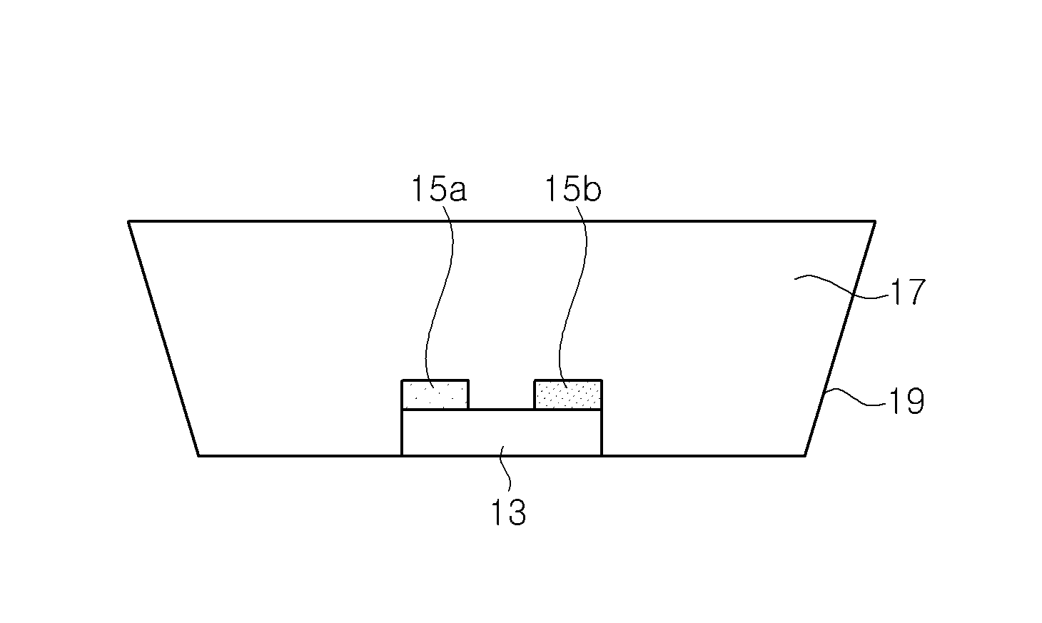
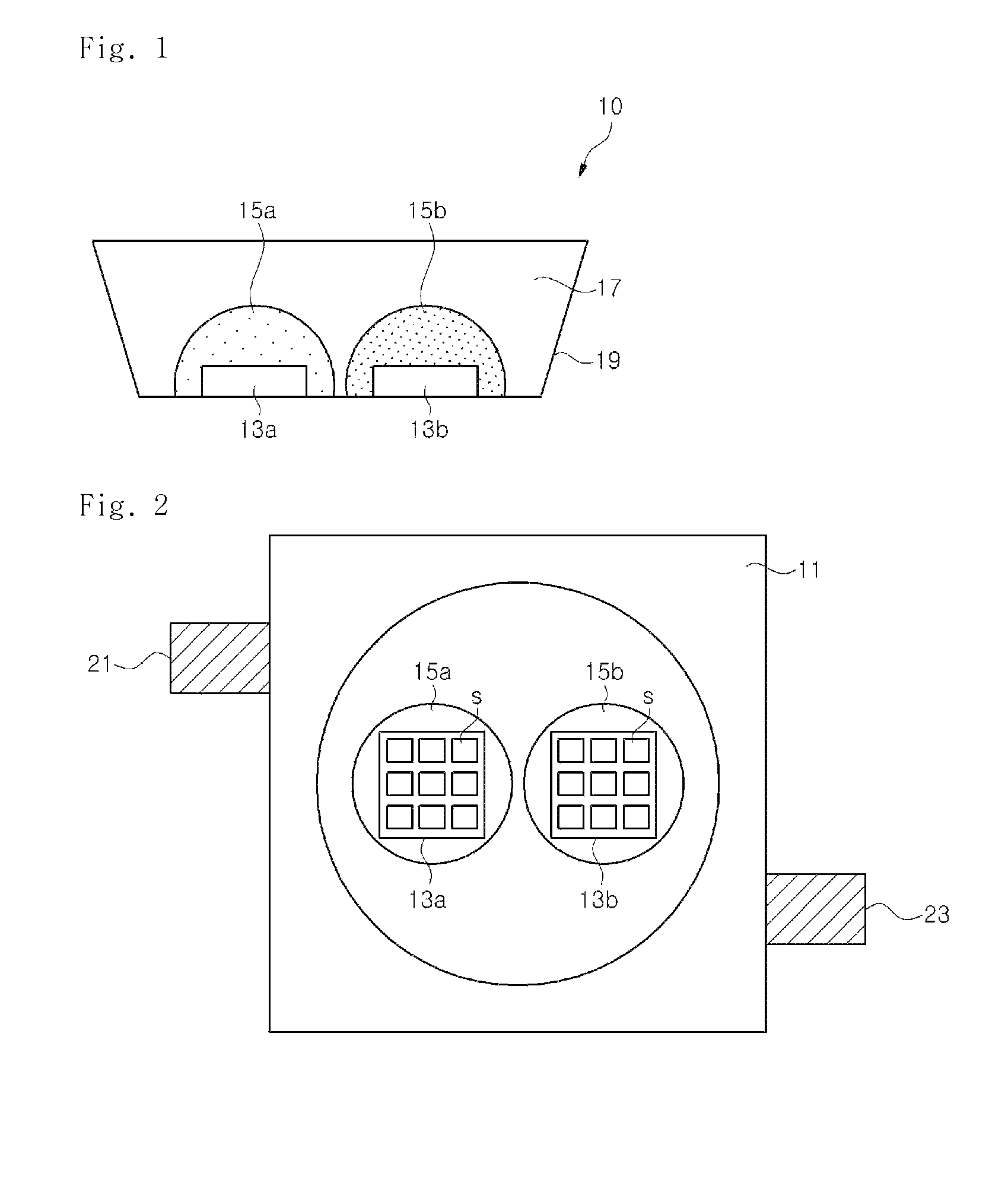
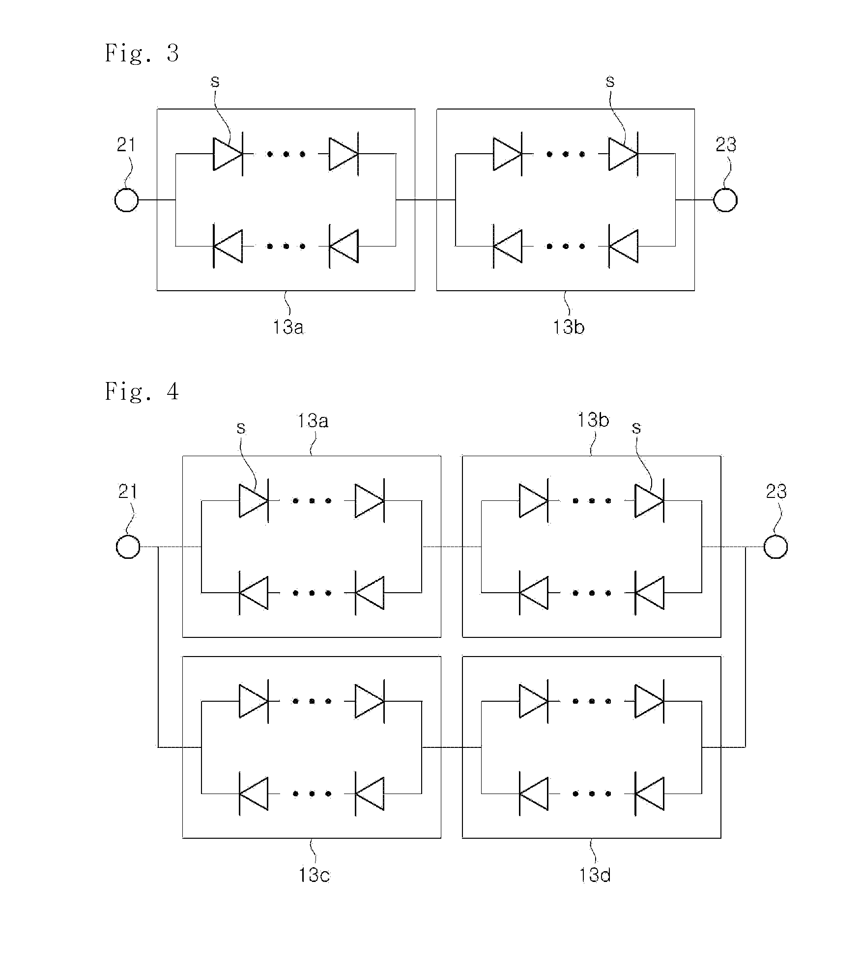
Disclosed are an AC light emitting device with a long-persistent phosphor and an AC light emitting device module having the same. According to an exemplary embodiment of the present invention, the light emitting device includes a first light emitting diode chip and a second light emitting diode chip, each of which has a plurality of light emitting cells on a single substrate. Further, a first long-persistent phosphor is positioned on the first light emitting diode chip to perform wavelength conversion for a portion of light emitted from the first light emitting diode chip; and a second long-persistent phosphor is positioned on the second light emitting diode chip to perform wavelength conversion for a portion of light emitted from the second light emitting diode chip. The afterglow luminescence resulted from the second long-persistent phosphor is allowed to be different from that resulted from the first long-persistent phosphor, whereby a flicker effect of the AC light emitting device can be more alleviated.

Description

CROSS-REFERENCE TO RELATED APPLICATIONS[0001]This application claims priority from and the benefit of Korean Patent Application No. 10-2008-0102837, filed on Oct. 21, 2008, and Korean Patent Application No. 10-2008-0108172, filed on Nov. 3, 2008, which are hereby incorporated by reference for all purposes as if fully set forth herein.BACKGROUND OF THE INVENTION[0002]1. Field of the Invention[0003]Exemplary embodiments of the present invention relate to a light emitting device, and more particularly, to an AC light emitting device in which a long-persistent phosphor is adopted to prevent a flicker effect and a light emitting device module having the same.[0004]2. Discussion of the Background[0005]Recently, a light emitting device that is directly connected to an alternating current (AC) power source to operate under AC power has been developed. Such a light emitting device includes a light emitting diode chip having a plurality of light emitting cells on a single substrate. The light...

Claims


Application Information

Patent Timeline
Patent Type & Authority Patents(United States)
IPC IPC(8): H05B33/14F21Y113/00H05B33/08H01L25/075F21K99/00H01L33/50H05B44/00
CPCF21K9/00H05B33/0821F21K9/56F21K9/54H01L2224/48137H01L25/0753H01L33/50F21Y2113/005H01L2224/49107F21V23/06H01L33/504F21K9/62F21K9/64F21Y2115/10F21Y2113/13H05B45/42
Inventor LEE, CHUNG HOONYOON, YEO JINKIM, DAE WONKAL, DAE SUNGYE, KYUNG HEE
Owner SEOUL VIOSYS CO LTD
Learn More