Deep-reading electromagnetic data acquisition method

a technology of electromagnetic data and deep reading, applied in the field of deep reading electromagnetic data acquisition method, can solve the problems of ineffective traditional tomographic imaging, and achieve the effect of reducing mismatches

Active Publication Date: 2014-08-19
SCHLUMBERGER TECH CORP +1
View PDF8 Cites 18 Cited by
  • Summary
  • Abstract
  • Description
  • Claims
  • Application Information

AI Technical Summary

Benefits of technology

[0017]A preferred method of inverting the obtained data includes the step of successively introducing bodies of water (or oil) into the background model to reduce the mismatch between modeled and the obtained crosswell electromagnetic signals. In a preferred variant the inversion is based on parametric inversion methods.
[0018]It is seen as an important advantage of the methods presented herein to provide a fast inversion within temporal proximity to the process of drilling an in-fill well into the volume between the two wells used for the EM survey evaluated. Hence, it is a further preferred feature of the invention that survey data can be inverted and / or evaluated to derive control parameters for a drilling process within days or even within hours of the data acquisition.

Problems solved by technology

In cases where the number of EM tomography measurements are limited by well access, a simplified model such as the above offers a practical means for data interpreting whereas traditional tomographic imaging would not be effective.

Method used


Image

  • Deep-reading electromagnetic data acquisition method
  • Deep-reading electromagnetic data acquisition method
  • Deep-reading electromagnetic data acquisition method

Examples


Embodiment Construction

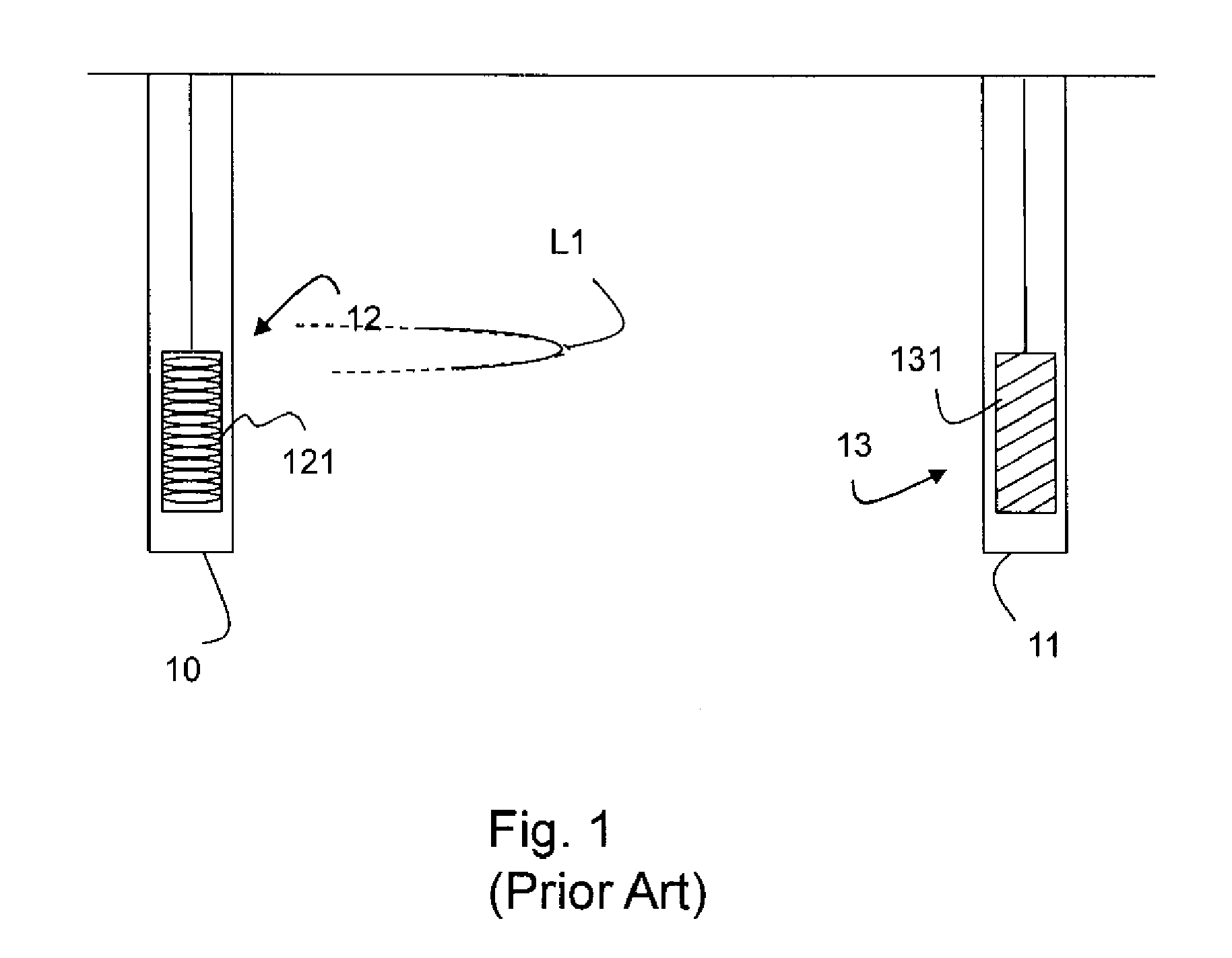
[0023]FIG. 1 shows the configuration of equipment used in the measurement of geologic formation resistivity between two boreholes 10, 11. A transmitter 12 is located in one borehole and consists of a coil 121 of NT turns with an effective cross section AT. The multi-turn loop carries an alternating current IT at a frequency of f0 Hz. This multi-turn horizontal loop produces a time varying magnetic field B0. The magnetic field B0 is proportional to the magnetic moment of the transmitter MT and to a geometric factor k1. The magnetic moment of the transmitter MT is defined as the product

MT=NT*IT*AT   [1].

[0024]The geometric factor k1 is a function of a spatial location and orientation of a field component of the magnetic field B0 measured by a receiver 13 with respect to the magnetic moment of the transmitter MT. The receiver is located separately from the transmitter 12 and typically disposed in a borehole in the earth. The magnetic field B0 is defined as follows:

B0=k1*MT   [2].

[0025]...


PUM


Abstract

A method of measuring a parameter characteristic of a rock formation is provided, the method including the steps of obtaining crosswell electromagnetic signals between two wells and using an inversion of said signals to investigate or delineate the presence of a resistivity anomaly, such as brine in a low resistivity background, wherein the resistivity anomaly is assumed to be distributed as one or more bodies characterized by a limited number of geometrical parameters and the inversion is used to determine said geometrical parameters. The method can also be applied to determine the trajectory of an in-fill well to be drilled.

Description

FIELD OF THE INVENTION[0001]This invention is generally related to the planning, acquisition, processing, and interpretation of geophysical data, and more particularly to methods for interpreting deep-reading electromagnetic data acquired during a field survey of the subsurfaceBACKGROUND[0002]Geologic formations defining a reservoir for the accumulation of hydrocarbons in the subsurface of the earth contain a network of interconnected paths in which fluids are disposed that ingress or egress from the reservoir. To determine the nature and behavior of the fluids in the aforementioned network, knowledge of both the nature of the pore fluids and the porosity of the geologic formations is desired. With this information, efficient development and management of hydrocarbon reservoirs may be achieved.[0003]For example, the electrical resistivity of geologic formations is a function of both porosity of the formations and resistivity of the fluids. Considering that hydrocarbons are electrica...

Claims


Application Information

Patent Timeline
Patent Type & Authority Patents(United States)
IPC IPC(8): G01V1/40G01V3/30
CPCG01V3/30
Inventor WILT, MICHAELMARSALA, ALBERTOCRARY, STEVEAL-RUWAILI, SALEH B.HABASHY, TAREK M.MA, SHOUXIANG
Owner SCHLUMBERGER TECH CORP
Why Eureka
Try Eureka