Nicotine inhaler and method of manufacture

a nicotine inhaler and nicotine technology, applied in the direction of inhalators, tobacco, other medical devices, etc., can solve the problems of failure to provide a friction or interference fit, failure to allow the product to be adequately sealed, and inability to provide friction or interference fit plugs or caps,

Active Publication Date: 2014-08-26
SMOKELESS
View PDF6 Cites 71 Cited by
  • Summary
  • Abstract
  • Description
  • Claims
  • Application Information

AI Technical Summary

Benefits of technology

[0015]The present invention is directed to a nicotine inhaler, its formation and a piercing tool used therewith, the inhaler including a tube sealed and impervious to nicotine having a cylindrical wall and closed ends. A filler is within the interior of the tube to carry nicotine that will allow evaporation with said evaporate being delivered to the user via inhalation. This device provides a structure which can have the feel of a cigarette and is able to retain volatile nicotine for an extended shelf life.

Problems solved by technology

However, the science and materials of his day would never allow his product to be adequately sealed to prevent the volatile liquid nicotine vapors from prematurely escaping within the tube to the open atmosphere before use.
However, without a hermetic seal, three days is all nature allows before the consumer will discover a tube container mostly depleted of vapor deliverables.
Even today, with the advanced chemical resistant materials available, a plug or cap that will provide a friction or interference fit is not understood to exist.
Any joint friction fit seal will fail.
Liquid nicotine is the reason this task is so difficult to accomplish.
This makes it an extremely deadly poison.
Thus, not only is liquid nicotine a poison that can attack or migrate through many materials, it also has a vapor pressure that further complicates containment within any sealed tube to be used as a cigarette substitute intended for consumers to breath released volatile vapors.
This can include jagged surfaces or burrs at the opening of the container which might cut or scratch the delicate skin surfaces of the user's mouth when contact with the container is made.

Method used


Image

  • Nicotine inhaler and method of manufacture
  • Nicotine inhaler and method of manufacture
  • Nicotine inhaler and method of manufacture

Examples


Embodiment Construction

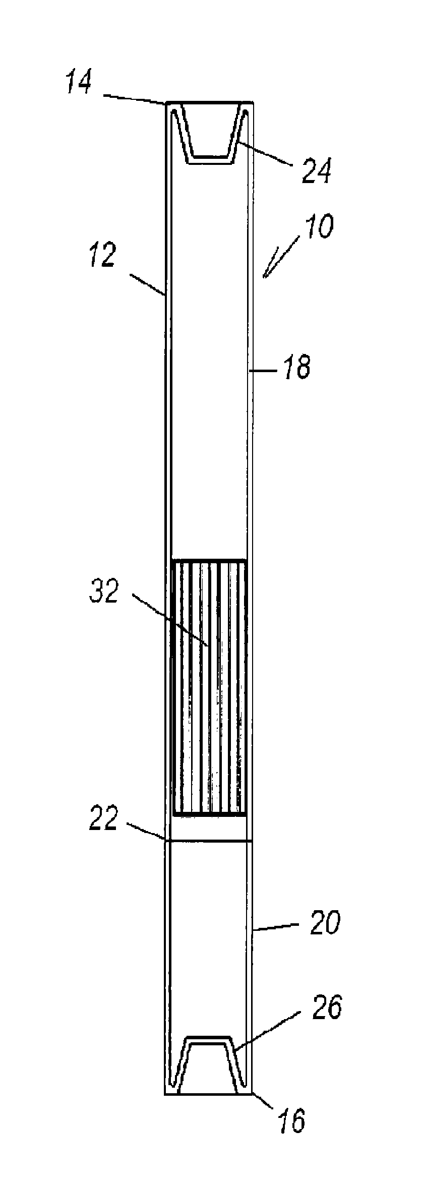
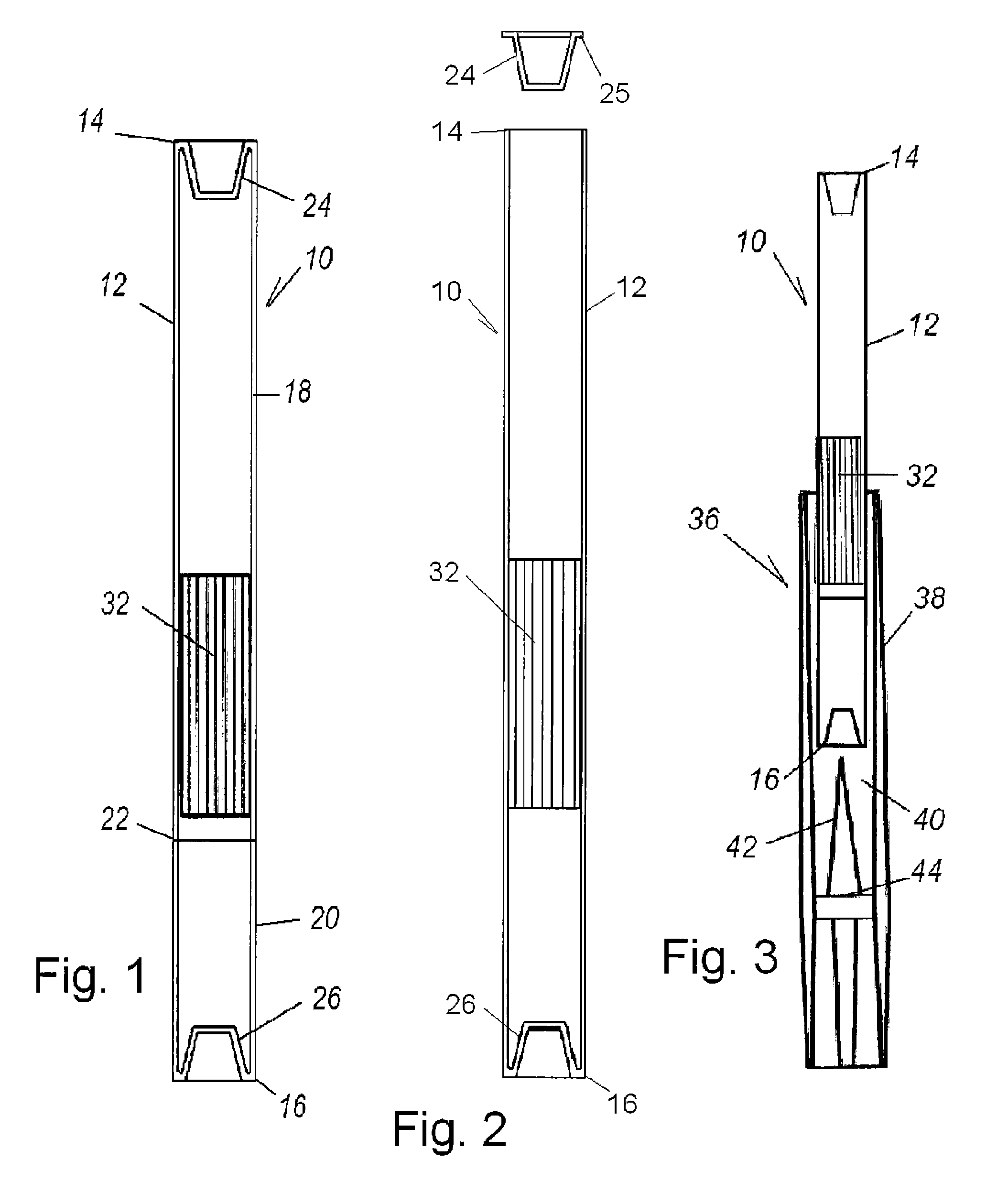
[0031]Turning in detail to the drawings, a nicotine inhaler includes a tube 10 which is sealed and impervious to nicotine. The tube 10 has a cylindrical wall 12 and two closed ends 14, 16. The tube 10 in the embodiment of FIG. 1 is of two molded or formed cylindrical portions 18, 20 heat fused together to form a butt-weld 22. Each cylindrical portion 18, 20 is a round cylinder in shape having one open end and one closed end wall 24, 26, formed with the respective tube element 18, 20. The first cylindrical portion 18 is approximately 0.250″-0.350″ in diameter and about 1″ long. The second cylindrical portion 20 is approximately 2″-3″ long of the same overall diameter. The wall thickness of both cylindrical portions 18, 20 can range from 0.015″-0.065″ with a preferred wall thickness approximately 0.025″-0.040″.

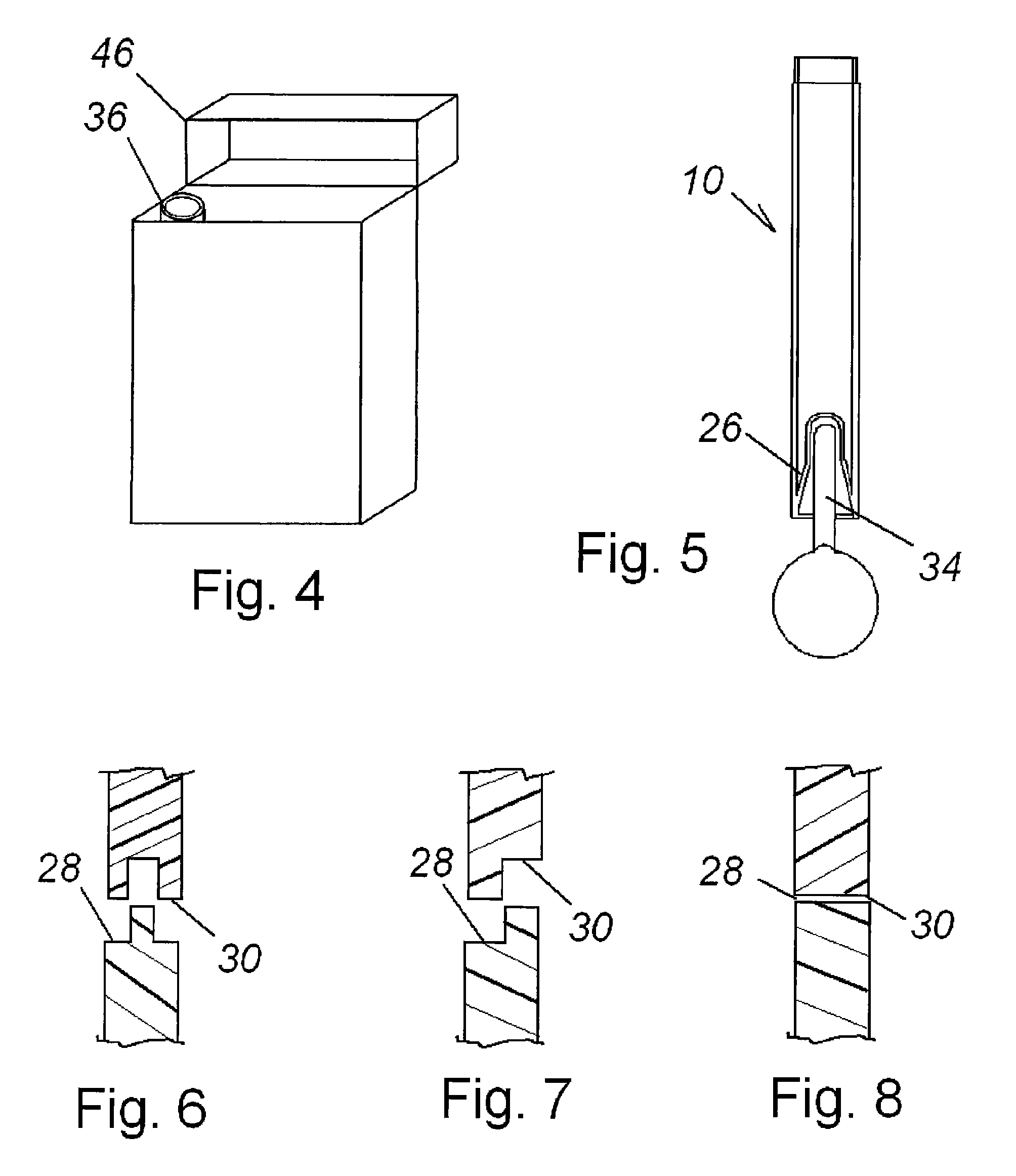
[0032]The open end wall face 28, 30 of each cylindrical portion 18, 20 has one of three shapes, as illustrated in FIGS. 6-8, intended to allow the joining of the two tube elemen...


PUM


Abstract

A self contained, hermetically sealed, cigarette shaped nicotine inhaler tube includes a cylindrical wall and formed closed ends. The two or more elements making up the tube are formed and sealed together after forming at a location between the closed ends, capturing a filler within. The filler is in the tube to carry nicotine. The closed ends are recessed from the end of the cylindrical tube and may be truncated conically shaped. The closed ends may be drawn further into the tube using heat and the pressure of a probe. A tool for piercing the ends of the tube includes a supportive cylindrical cavity slightly larger than the tube with a centric spike and a terminal surface in the cavity. The cylindrical wall of the tube is supported by the cavity and the truncated conical shape of the end wall to receive the spike for penetrating the end wall at each end. The terminal surface prevents excessive penetration of the spike.

Description

BACKGROUND OF THE INVENTION[0001]The field of invention is cigarette substitute nicotine inhaler tubes.[0002]There are three patented concepts that define the field of invention regarding non-mechanical nicotine inhaler cigarette substitutes: U.S. Pat. No. 2,445,476 to Folkman; U.S. Pat. No. 6,769,436 to Horian and U.S. Pat. No. 5,400,808 to Turner, with continuations U.S. Pat. Nos. 5,501,236 and 6,098,632, all the foregoing Patents being incorporated herein by reference. These devices each define a self contained cigarette shaped open air tube inhaler designed to deliver evaporate to the user released from liquid nicotine contained within the tube.[0003]It was Marvin L. Folkman (U.S. Pat. No. 2,445,476—1958) who may be first credited with the concept of a cigarette substitute meant to replace ignitable cigarettes by using liquid nicotine contained in a cigarette shaped tube and breathing air through the tube to deliver nicotine evaporate to the user. He first teaches an absorbent o...

Claims


Application Information

Patent Timeline
Patent Type & Authority Patents(United States)
IPC IPC(8): A24F47/00A61M15/06A24F42/20A24F42/60
CPCA61M15/06A61M2205/8268A24F47/00A61M11/047A61M15/0035A24F47/002A24F42/20A24F42/60
Inventor HORIAN, RICHARD, C.
Owner SMOKELESS
Why Eureka
Try Eureka