Device and process for touch and proximity detection

a technology of proximity detection and proximity detection, applied in the direction of heating fuel, heating details, heating types, etc., can solve the problems of inability to always ensure the threshold of reaching the switching threshold, the signal level of the capacitive switch oscillates, and the distinction between approach and touch is no longer possible. , to achieve the effect of simple entry into the cooktop

Active Publication Date: 2014-09-02
MICROCHIP TECH GERMANY II
View PDF7 Cites 21 Cited by
  • Summary
  • Abstract
  • Description
  • Claims
  • Application Information

AI Technical Summary

Benefits of technology

[0009]Therefore, it is an object of the invention to provide a capacitive switch or a capacitive switch device, especially for a cooktop, in which on the one hand reaching a predetermined switching threshold can be ensured independently of coupling fluctuations of the capacitive coupling between the operator and the capacitive switch device and on the other hand a clear distinction is possible between an approach and a touch, and which can be integrated in a simple way into the cooktop.SOLUTION ACCORDING TO THE INVENTION
[0023]It is advantageous that a touch / proximity switch may be covered by a control panel, ensuring nevertheless that an approach to the switch may be distinguished from a touch of the switch.
[0025]The detection means may be capacitively coupled with the modulation device. That has the advantage that switch elements (detector electrode, auxiliary electrode and modulation device) are mounted independently of the detection means.
[0030]It is advantageous if the auxiliary electrode is substantially parallel to and arranged at a predetermined distance from the detector electrode.
[0040]In this way a switch device is provided, which thanks to a particularly compact design and the capacitive coupling to the receiving device may be arranged in a simple and particularly space saving way below the cooktop.
[0054]A number of capacitive circuit components may be arranged in such a way at the bottom of a cooktop, wherein the activation of the single circuit components is done by applying a conductive structure at the top surface of the cooktop. The conductive structures are applied at the top surface in such a way that they are situated substantially exactly opposite the circuit components. By the capacitive coupling between the conductive structures and the respective circuit components the approach of the operator to a conductive structure may be detected by the corresponding capacitive circuit component. Circuit components, to which no conductive structure is assigned, may be deactivated in this way. In this way it is possible to provide unified structures of circuit components for different equipment variants of cooktops, wherein the activation is done by means of conductive structures at the top surface of the cooktop.

Problems solved by technology

Here the disadvantage is, however, that by coupling fluctuations of the capacitive coupling, for example between the finger and the capacitive switch, the signal levels of the capacitive switches oscillate and reaching the switching threshold cannot be always ensured.
Another disadvantage consists of the fact that when mounting a capacitive switch behind a control panel, for example a glass sheet, a distinction between approach and touch is no longer possible.

Method used


Image

  • Device and process for touch and proximity detection
  • Device and process for touch and proximity detection
  • Device and process for touch and proximity detection

Examples


Embodiment Construction

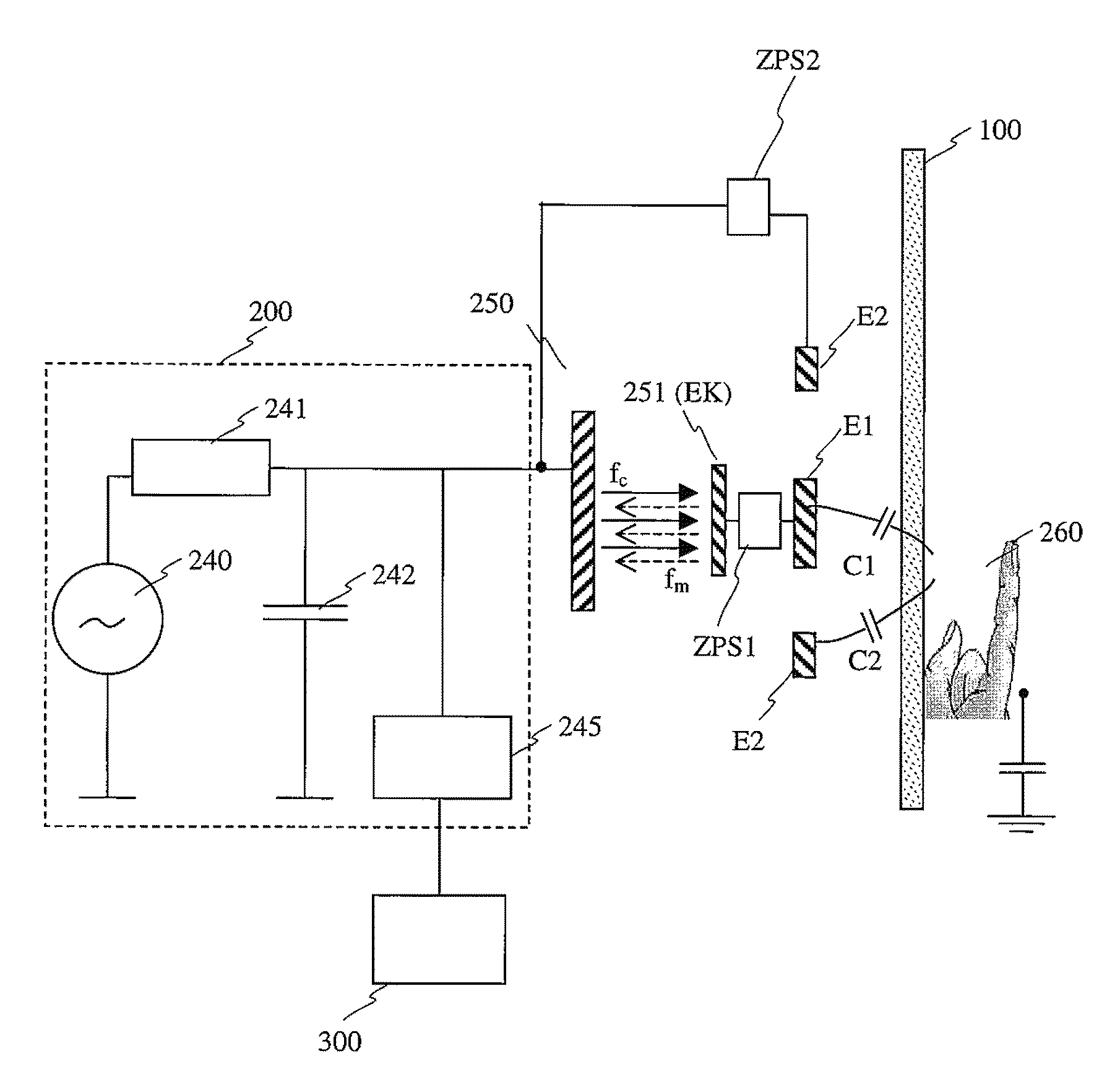
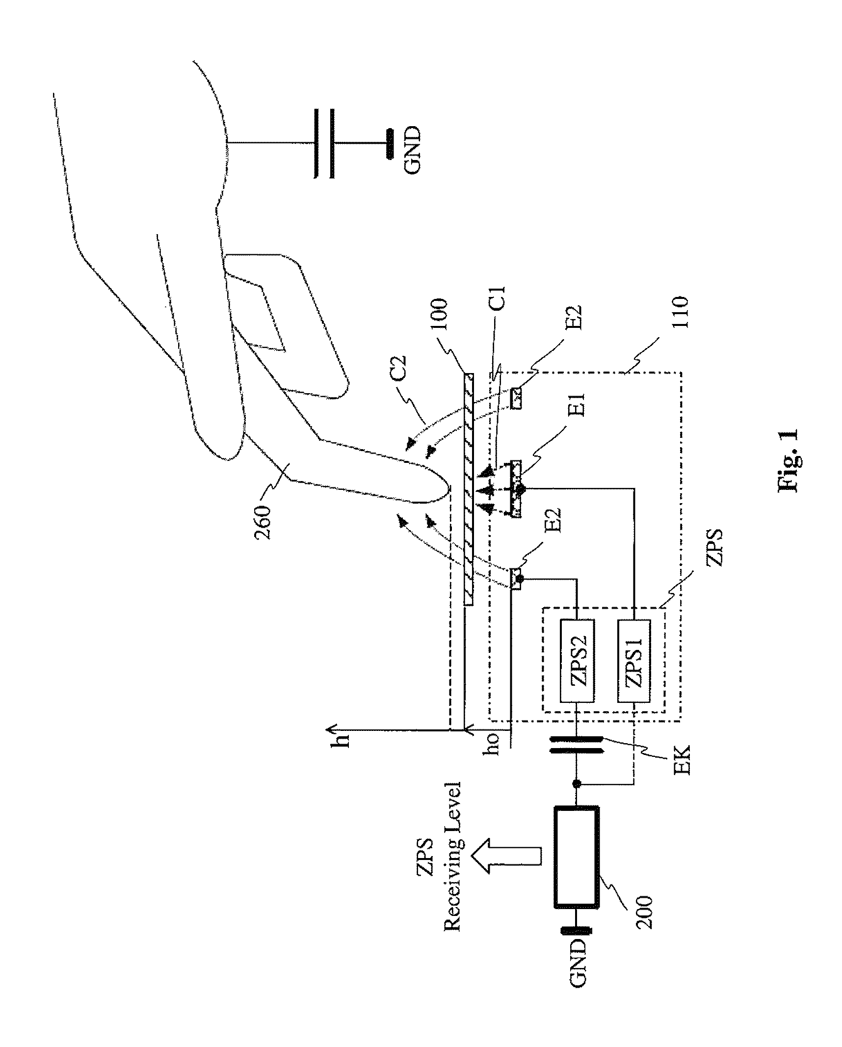
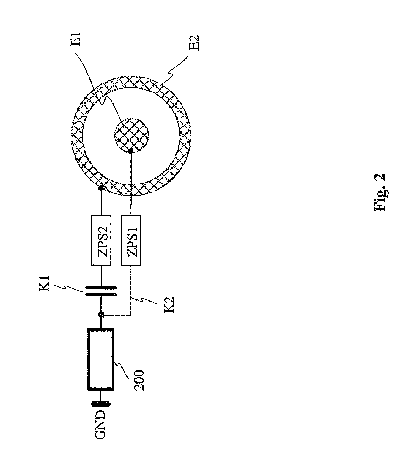
[0073]FIG. 1 shows an embodiment of the capacitive switch device according to the invention. The switch device comprises a detection means 200 and a switch element 110. The switch element 110 is formed of two electrodes E1 and E2, which each time are coupled with a modulation device ZPS1 and ZPS2. The two modulation devices ZPS1 and ZPS2 may be coupled either capacitively (like the modulation device ZSP2) or galvanically (like the modulation device ZSP1) with the detection means 200.

[0074]In case of a capacitive coupling of a modulation device with the detection means 200, the modulation device presents a coupling-in electrode EK, to which an electrical alternating field emitted by the detection means 200 may be coupled. With this electric alternating field, with a corresponding design of the modulation device, the latter is also supplied with energy.

[0075]By means of the coupled alternating electric field the load of the detection means 200 is modulated by the modulation device. In...


PUM


Abstract

The invention relates to a device for touch / proximity detection, especially a capacitive switch device, which is designed to set switching states by approaching the switch device or by touching the switch device, in order to perform, for example, switching actions on an instrument. The invention also relates to a switch device, especially a switch device on a capacitive basis, for a cooktop, for operating the cooktop.

Description

CROSS REFERENCE TO RELATED APPLICATIONS[0001]This application is the US national phase of PCT application PCT / EP2009 / 062649, filed 29 Sep 2009, published as 102008052324.0, and claiming the priority of German patent application 102008050181.6itself filed 1 Oct 2008 and German patent application 102008050186.7 itself filed 1 Oct 2008, whose entire disclosures are herewith incorporated by reference.FIELD OF THE INVENTION[0002]The invention relates to a device for touch / proximity detection, especially to a capacitive switch device, which adjusts switching states by approaching the switch device or by touching the switch device, in order to perform, for example, switching actions on an instrument.[0003]The invention also relates to a switch device, especially a switch device on a capacitive basis, for a cooktop for operating the cooktop.STATE OF THE ART[0004]Capacitive switches are known in various types from prior art. In order to adjust a switching state, it is known to set a fixed le...

Claims


Application Information

Patent Timeline
Patent Type & Authority Patents(United States)
IPC IPC(8): G01R27/26F24C7/08F24C15/10H03K17/955H03K17/96
CPCH03K17/962H03K17/955F24C7/082F24C15/102H03K2217/94089H03K2217/96073F24C7/086H03K2217/96077H03K2217/960705H03K2217/960765
Inventor AUBAUER, ROLANDSCHWAIGER, HANS
Owner MICROCHIP TECH GERMANY II
Why Eureka
Try Eureka