Circuit arrangement and method for transmitting TMDS encoded signals

a technology of tmds and encoded signals, applied in the direction of transmission systems, fibre transmission, transmission, etc., can solve the problems of high-quality and thus expensive copper cables to be used

Active Publication Date: 2014-09-02
SILICON LINE
View PDF56 Cites 19 Cited by
  • Summary
  • Abstract
  • Description
  • Claims
  • Application Information

AI Technical Summary

Benefits of technology

[0012]Starting from the above-explained disadvantages and inadequacies and in consideration of the prior art outlined, the object of the present invention is to provide a circuit arrangement and a method for inexpensively transmitting signals from at least one data source to at least one data sink, said signals being TMDS encoded at least in part, in particular at least in a time slot manner, and in particular being assigned to at least one DVI data connection and / or to at least one HDMI data connection.
[0070]The circuit arrangement with the at least one driver circuit according to the present invention and with the at least one transimpedance converter circuit according to the present invention represents a possibility to optically transmit the TMDS signals provided by the connection interface of the data source, without requiring an additional external current supply therefor.
[0071]Due to the fact that TMDS encoded signals can comprise data rates in the region of several gigabits per second, the optical transmission, as enabled by means of the present invention, of such TMDS encoded signals via optical fibers permits the buildup of inexpensive signal connections, which do not emit electromagnetic radiation and which can transport high data rates with low attenuation from the data source to the data sink. The advantages due to the presently optical transmission have an effect in particular for cable lengths of more than about three meters.

Problems solved by technology

This involves that highest-quality and thus expensive copper cables are to be used in case of longer distances between data source and data sink.

Method used


Image

  • Circuit arrangement and method for transmitting TMDS encoded signals
  • Circuit arrangement and method for transmitting TMDS encoded signals
  • Circuit arrangement and method for transmitting TMDS encoded signals

Examples


Embodiment Construction

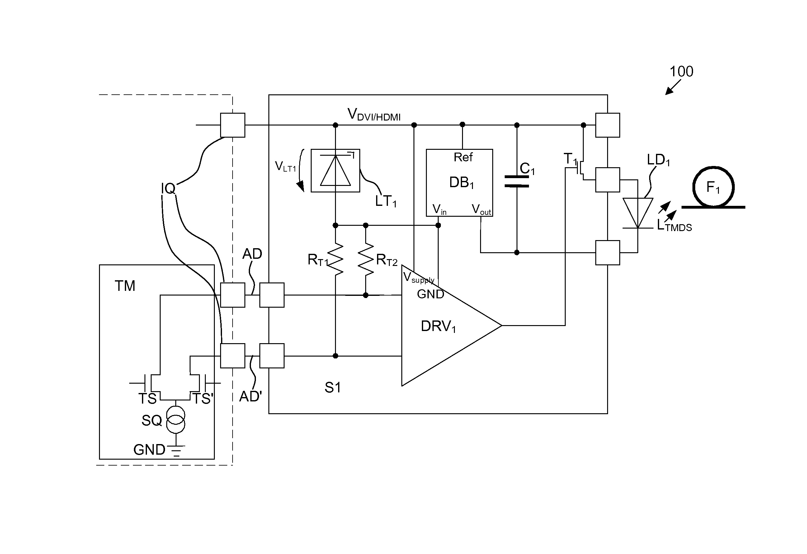
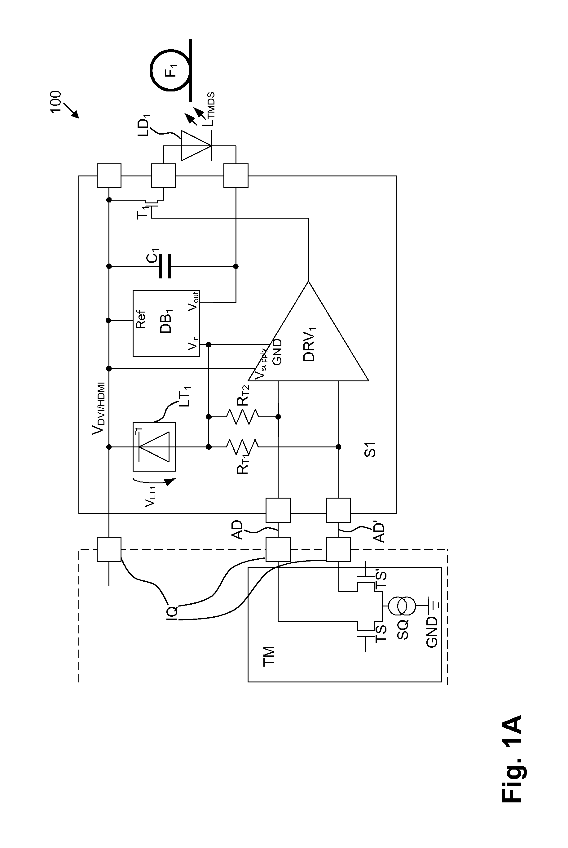
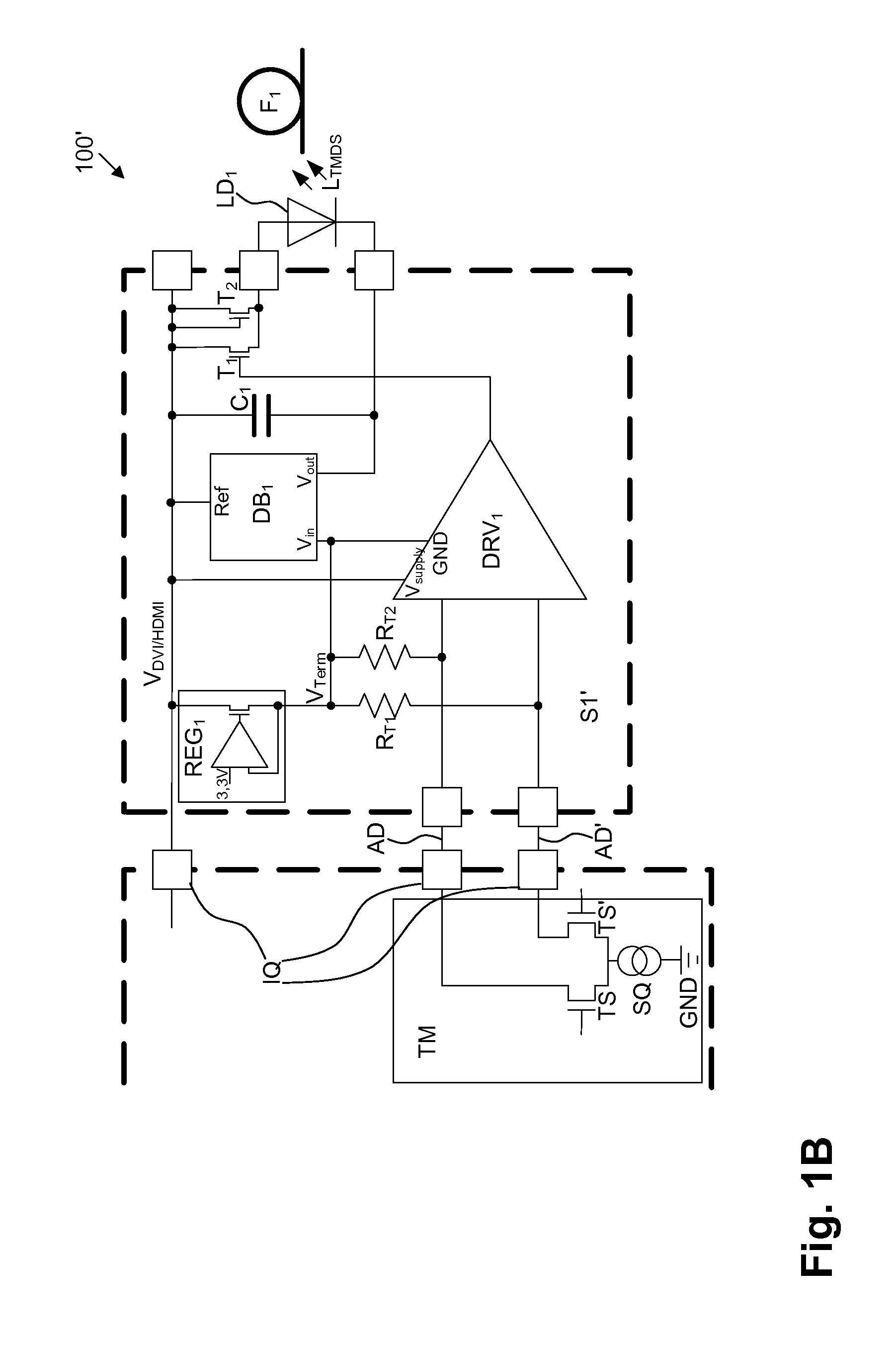
[0087]By means of the driver circuit S1 illustrated by FIG. 1A or of the driver circuit S1′ illustrated by FIG. 1B according to the present invention, and by means of the transimpedance converter circuit S2 illustrated by FIG. 2A or of the transimpedance converter circuit S2′ illustrated by FIG. 2B according to the present invention, which together define the circuit arrangement 100 (cf. FIG. 1A, FIG. 2A) or the circuit arrangement 100′ (cf. FIG. 1B, FIG. 2B) according to the present invention (within the scope of the present invention, it is possible to implement and to operate the driver circuit S1, S1′ and the transimpedance converter circuit S2, S2′ independently of each other), it is basically possible to implement and to operate a cable-based connection without the necessity of any further electrical supply—apart from the electrical supply anyway already present at the electrical contacts—and thus to fit in at least one DVI and / or HDMI transmission channel of an active optical...


PUM


Abstract

For providing circuit arrangement and method for transmitting signals from a data source to a data sink, the signals being TMDS encoded, the driver circuit is supplied by a connection interface, connected upstream, assigned to data source, with supply voltage, electrical TMDS encoded signals are electro-optically converted by an LED connected downstream of the driver circuit and coupled into an optical fiber as light supplied with TMDS encoded signals, the direct current portion supplied from TMDS transmitter to connection interface, to data source, is converted by driver circuit to a modulated signal current for controlling LED. Light supplied with TMDS encoded signals decoupled out from optical fiber by light-absorbing element, opto-electrically converted and supplied to transimpedance converter circuit connected downstream of light-absorbing element and upstream of connection interface assigned to data sink, transimpedance converter circuit being supplied by direct voltage portion being applied to differential pair of wires.

Description

CROSS-REFERENCE TO RELATED APPLICATIONS[0001]This application is a continuation of application no. PCT / EP2009 / 063131, filed 9 Oct. 2009, which claims the priority of German application no. 10 2008 042 724.1, filed 9 Oct. 2008, and which application no. PCT / EP2009 / 063131, filed 9 Oct. 2009, claims the priority of German application no. 10 2009 029 683.2, filed 22 Sep. 2009, and each of which is incorporated herein by reference.FIELD OF THE INVENTION[0002]The present invention relates to a circuit arrangement for transmitting signals from at least one data source to at least one data sink, said signals being TMDS encoded at least in part, in particular at least in a time slot manner, and in particular being assigned to at least one DVI data connection and / or to at least one HDMI data connection (DVI=Digital Visual Interface; HDMI=High Definition Multimedia Interface; TMDS=Transition-Minimized Differential Signaling).[0003]The present invention further relates to a method for transmitt...

Claims


Application Information

Patent Timeline
Patent Type & Authority Patents(United States)
IPC IPC(8): H04B10/00H04B10/2575
CPCG09G5/006G09G2370/04G09G2370/12H04B10/25751H04N21/42607G09G2370/18
Inventor GROEPL, MARTINHOELTKE, HOLGER
Owner SILICON LINE
Why Eureka
Try Eureka