
Method and device for low-temperature air separation

Inactive Publication Date: 2014-09-09
LINDE AG
View PDF8 Cites 0 Cited by
  • Summary
  • Abstract
  • Description
  • Claims
  • Application Information

AI Technical Summary

Benefits of technology

The invention aims to increase the amount of oxygen produced from an air separation plant without needing to add extra equipment or heat exchangers. By connecting certain parts of the plant, the prePixelation (when air is heated and cooled before being separated) is minimized, which leads to a higher yield of oxygen.

Problems solved by technology

Therefore, the preliquefaction has an adverse effect on the rectification processes in the double column.
The efficiency and economic efficiency of the air separation plant decrease.
These measures, however, mean a higher energy consumption and make the overall plant more expensive as a result of a higher number of heat exchangers and / or machinery.

Method used


Image

  • Method and device for low-temperature air separation
  • Method and device for low-temperature air separation
  • Method and device for low-temperature air separation

Examples


Embodiment Construction

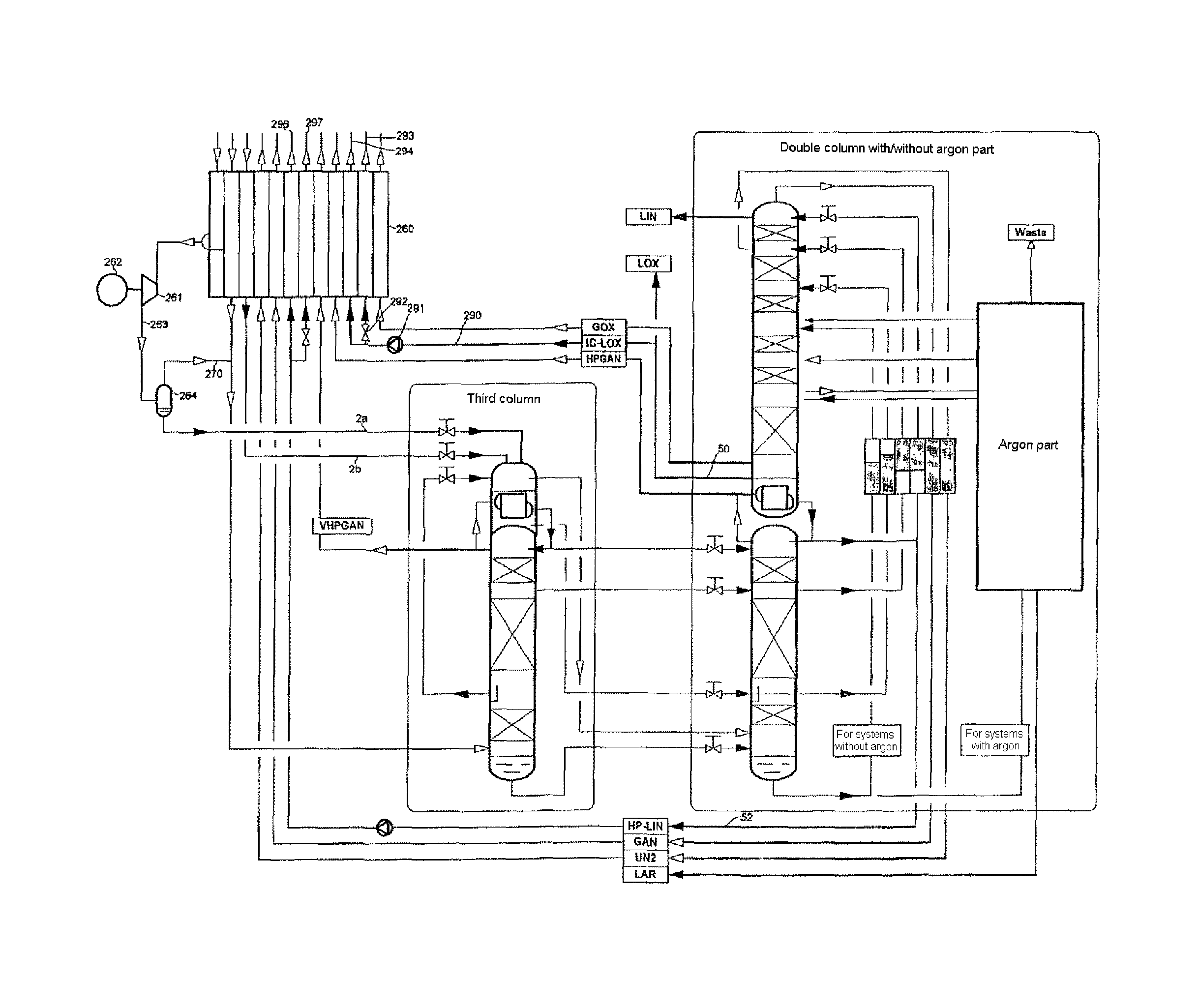
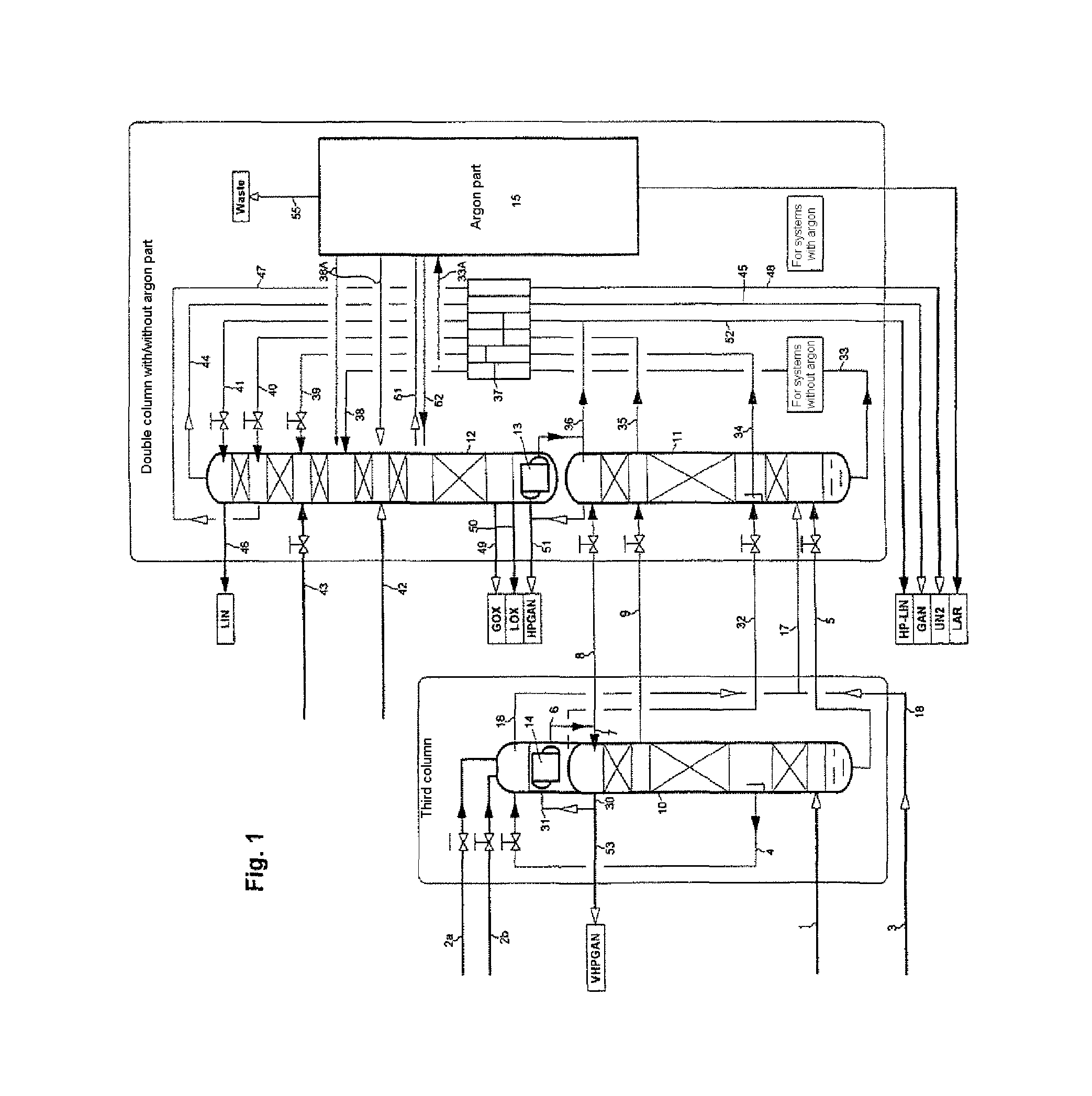
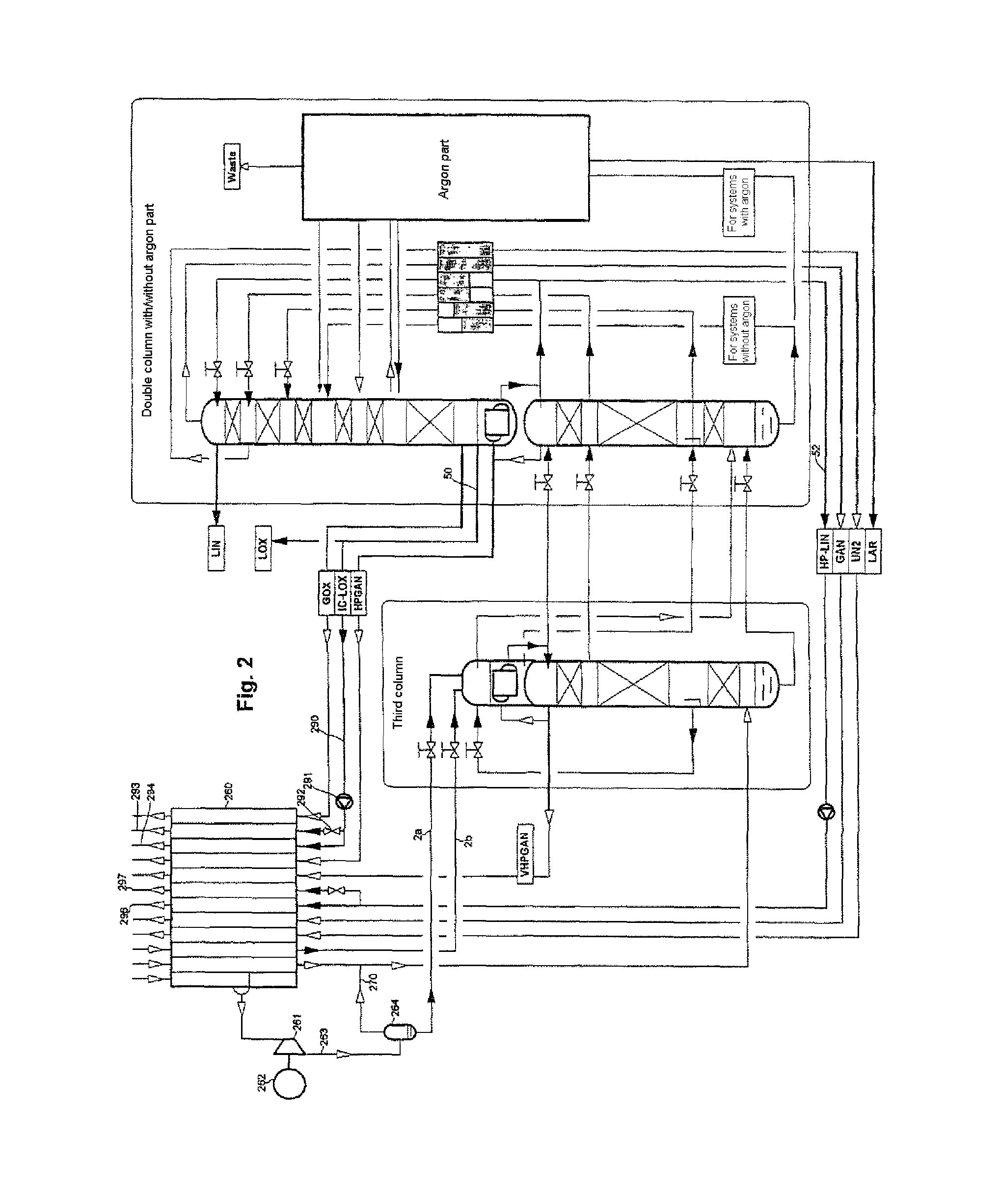
[0041]In FIG. 1, the compression, purification and cooling of the feed air is not shown. The distillation column system comprises here a precolumn 10, a high-pressure column 11 and a low-pressure column 12, and also the condenser-evaporator linked thereto, the main condenser 13 and the top condenser 14 of the precolumn. Optionally, the distillation column system can additionally comprise an argon part 15 which contains, in particular, at least one crude argon column and top condenser thereof; in addition, the argon part can comprise a pure argon column for argon / nitrogen separation.

[0042]The separation columns for nitrogen / oxygen separation in the example have the following operating pressures (in each case at the top):

[0043]

precolumn 107.5 to 12 bar,high-pressure column 115.0 to 6.5 bar,low-pressure column 121.3 to 1.6 bar.

[0044]A first substream 1 of the feed air comes in the gaseous state from the cold end of the main heat exchanger (which is not shown) or from a turbine. It is a...


PUM


Abstract

The invention relates to a method and a device used for the low-temperature separation of air in a distillation column system, comprising at least one high-pressure column (11) and a low-pressure column (12). The method has a high pre-liquifaction of 30% or more. Feed air is introduced into the distillation column system. The distillation column system further has a pre-column (10), the operating pressure of which is higher than the operating pressure of the high-pressure column (11). A first partial stream (1) of the feed air is introduced into the pre-column (10). The pre-column (10) has a head condenser (14), which is configured as a condenser-evaporator having a condensation chamber and an evaporation chamber. A gaseous fraction (30, 31) from the upper region of the pre-column (10) is introduced into the condensation chamber of the head condenser (14). Fluid (6) formed in the condensation chamber is at least partially applied to the pre-column (10) as runback (7). A second partial stream (2a; 2b) of the feed air is introduced into the evaporation chamber of the head condenser (14).

Description

[0001]This U.S. patent application is a national stage application of PCT / EP2009 / 000431 filed on 23 Jan. 2009 and claims priority of both European patent document 08009400.6 filed on 19 Jun. 2008 and German patent document 10 2008 006 431.9 filed on 28 Jan. 2008, the entireties of which are incorporated herein by reference.FIELD OF INVENTION[0002]The invention relates to a method for low-temperature separation of air.BACKGROUND OF THE INVENTION[0003]Methods and devices for low-temperature separation of air are known, for example, from Hausen / Linde, Tieftemperaturtechnik [Low-temperature technology], 2nd edition 1985, Chapter 4 (pages 281 to 337).[0004]The distillation column system of the invention comprises a two-column system (for example a classical Linde double-column system) for separating nitrogen / oxygen having a high-pressure column and a low-pressure column which are in a heat-exchange relationship with one another. The heat-exchange relationship between high-pressure column...

Claims


Application Information

Patent Timeline
IPC IPC(8): F25J3/00F25J3/04
CPCF25J3/04442F25J2240/40F25J3/04175F25J3/04872F25J3/04303F25J3/04084F25J2205/04F25J3/0409F25J3/04709F25J3/04296F25J3/04878F25J3/04393F25J3/04375F25J3/00F25J3/04F25J3/0403
Inventor ALEKSEEV, ALEXANDER
Owner LINDE AG
Learn More