Oxygen production method and apparatus

a technology of oxygen production method and apparatus, which is applied in the direction of lighting and heating apparatus, solidification, refrigeration and liquid reaction, etc., can solve the problems of simple plant replication, reducing the oxygen production capacity of the air separation plant, so as to reduce the vapor load, increase the oxygen production, and reduce the effect of vapor loading

Active Publication Date: 2014-09-02
PRAXAIR TECH INC
View PDF10 Cites 0 Cited by
  • Summary
  • Abstract
  • Description
  • Claims
  • Application Information

AI Technical Summary

Benefits of technology

[0010]The present invention allows for an increase in oxygen production within a multiple plant installation in which a single auxiliary column is used to divert nitrogen from the lower pressure columns within the installation by the production of an oxygen-rich liquid that is fed into the lower pressure columns. The diversion of the nitrogen from the lower pressure column in turn reduces vapor loadings within the nitrogen rectification sections of such columns to increase plant capacity. It has been calculated that the use of such an auxiliary column could increase plant capacity between 25 and 30 percent of each of the plants located in the installation. As can be appreciated, in a multiple plant installation, this increase in capacity could save the use of a plant in the installation and would therefore reduce the costs involved in constructing the installation.

Problems solved by technology

Shipping limitations result in a maximum vessel diameter in the range of 6.0 to 6.5 m. As a consequence, the design, construction and installation of an air separation plant having an oxygen production capacity in excess of about 5000 metric tons per day has not been found to be practical.
Unfortunately simple plant replication forfeits many “economies of scale” in that the construction of additional column shells carries with it considerable expense.
A critical limitation associated with a distillation column involves the hydraulic flood point of any given column section.
Given a fixed maximum diameter and packing selection, such sections will limit capacity of each plant.

Method used


Image

  • Oxygen production method and apparatus
  • Oxygen production method and apparatus

Examples


Embodiment Construction

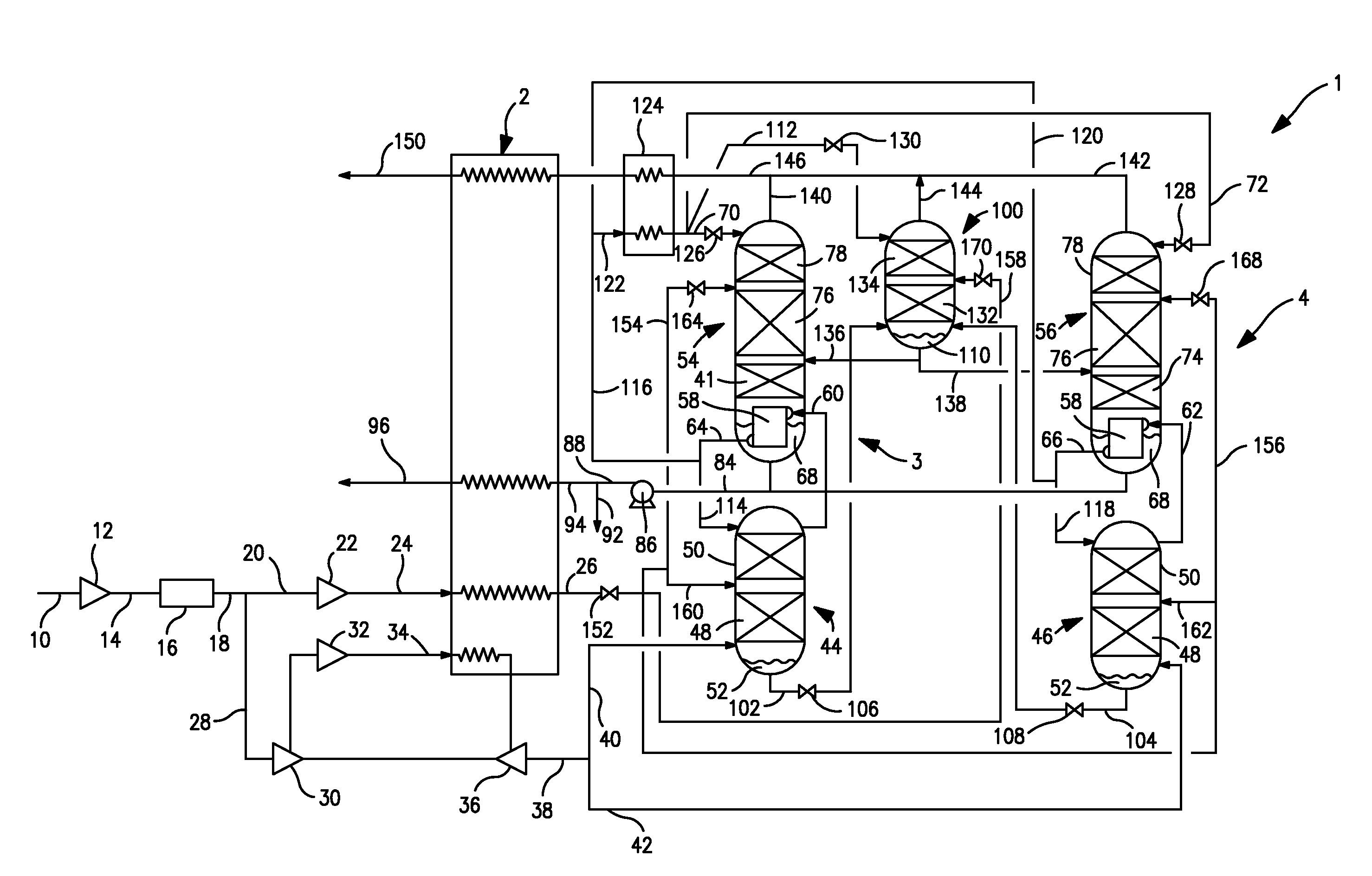
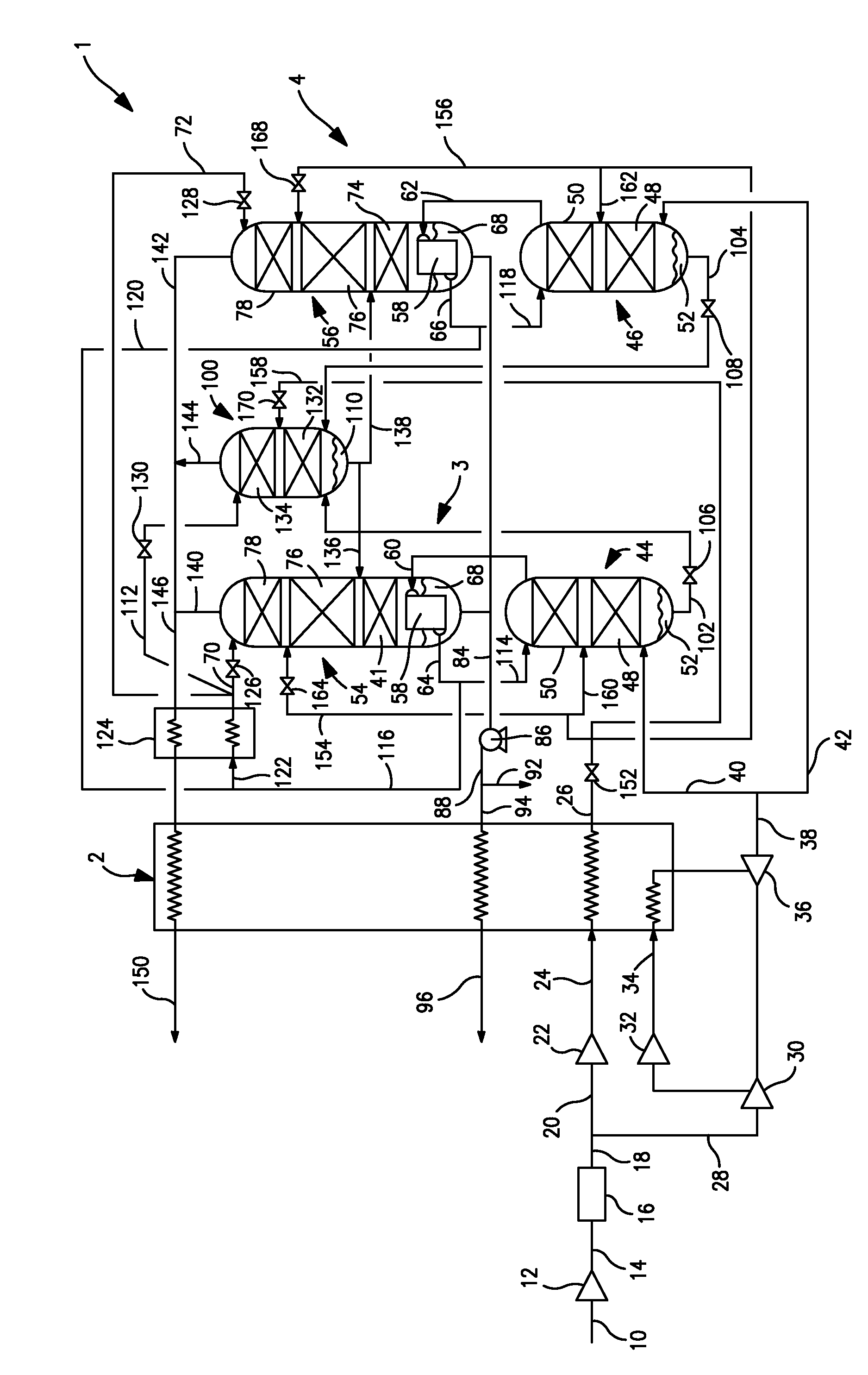
[0025]With reference to the FIGURE, a cryogenic rectification installation 1 is illustrated that is designed to separate air and thereby to produce an oxygen product. Cryogenic rectification installation 1 is provided with a main heat exchanger 2 to cool the air to a temperature suitable for its rectification within air separation units 3 and 4 and thereby produce an oxygen product that is discharged from the main heat exchanger 2 as an oxygen product stream 96, to be discussed in more detail hereinafter.

[0026]The air to be separated is introduced into apparatus 1 as an air stream 10 that is compressed in a main compressor 12 to produce a main compressed air stream 14 having a pressure in a range of from between about 5 and about 15 bar(a). Main compressor 12 can be a multi-stage intercooled integral gear compressor with condensate removal. Main compressed air stream 14 is subsequently purified in a pre-purification unit 16 to remove higher boiling impurities such as water vapor, ca...


PUM


Abstract

A method and apparatus for producing an oxygen product in which air is separated in an installation including air separation units having higher and lower pressure columns. A pumped liquid stream generated within the installation, that can be a pumped liquid oxygen stream, is warmed within a main heat exchanger through indirect heat exchange with a compressed air stream to produce a liquid air stream. An impure oxygen stream is rectified within an auxiliary column to produce an oxygen containing stream that is introduced into the lower pressure column of each of the air separation units and intermediate liquid streams, composed of the liquid air stream or another air-like stream, reflux the lower pressure columns and the auxiliary column and optionally the higher pressure column of each of the air separation units.

Description

FIELD OF THE INVENTION[0001]The present invention relates to a method of producing an oxygen product and an apparatus to conduct such method. More particularly, the present invention relates to such a method and apparatus in which multiple air separation units, each having a higher and a lower pressure columns, are connected to an auxiliary column that produces oxygen containing streams that are lean in nitrogen and that are introduced into the lower pressure columns to allow the air separation units to operate at a higher capacity.BACKGROUND OF THE INVENTION[0002]Large quantities of oxygen are required for purposes of coal gasification, production of synthetic liquid fuels and in combustion processes involving the use of oxygen. In certain of the foregoing processes, upwards of between 10,000 and 15,000 metric tons per day of oxygen can be consumed.[0003]The cryogenic rectification of air is the preferred method for large scale oxygen production. In cryogenic rectification, air is ...

Claims


Application Information

Patent Timeline
Patent Type & Authority Patents(United States)
IPC IPC(8): F25J3/00F25J3/04
CPCF25J3/04084F25J3/04957F25J3/0423F25J3/04951F25J3/0409F25J3/04296F25J3/04412F25J3/04872F25J3/04963F25J2200/32F25J2205/30F25J2245/42F25J3/04175
Inventor HOWARD, HENRY EDWARDJIBB, RICHARD JOHN
Owner PRAXAIR TECH INC
Why Eureka
Try Eureka