Method for calibrating a superheat sensor

a superheat sensor and sensor technology, applied in the direction of material thermal analysis, lighting and heating apparatus, instruments, etc., can solve the problems of increasing manufacturing costs, affecting the quality of products, so as to reduce the load, reduce the amount of liquid refrigerant in the evaporator, and reduce the evaporation of refrigeran

Inactive Publication Date: 2014-09-09
DANFOSS AS
View PDF24 Cites 8 Cited by
  • Summary
  • Abstract
  • Description
  • Claims
  • Application Information

AI Technical Summary

Benefits of technology

[0009]It is a further object of the invention to provide a method for calibrating a superheat sensor, in which the risk of introducing errors is reduced as compared to prior art methods.
[0031]As another alternative, the step of increasing an amount of liquid refrigerant in the evaporator may comprise decreasing a rotational speed of the compressor. When the rotational speed of the compressor is decreased the suction pressure of the refrigeration system is increased. The increased suction pressure causes the evaporation temperature to increase, thereby reducing the temperature difference across the evaporator of the refrigerant. Thereby the evaporation of refrigerant is decreased, and this increases the amount of liquid refrigerant in the evaporator.

Problems solved by technology

In the case that liquid refrigerant is allowed to exit the evaporator there is a risk that this liquid refrigerant reaches the compressor, and this may in some cases cause damage to the compressor.
This is cumbersome and increases the manufacturing costs.
This increases the component count for the sensor, and it is cumbersome.
However, this introduces a considerate risk of introducing errors originating from a mismatch between a sensor and calibration information.

Method used


Image

  • Method for calibrating a superheat sensor
  • Method for calibrating a superheat sensor
  • Method for calibrating a superheat sensor

Examples


Embodiment Construction

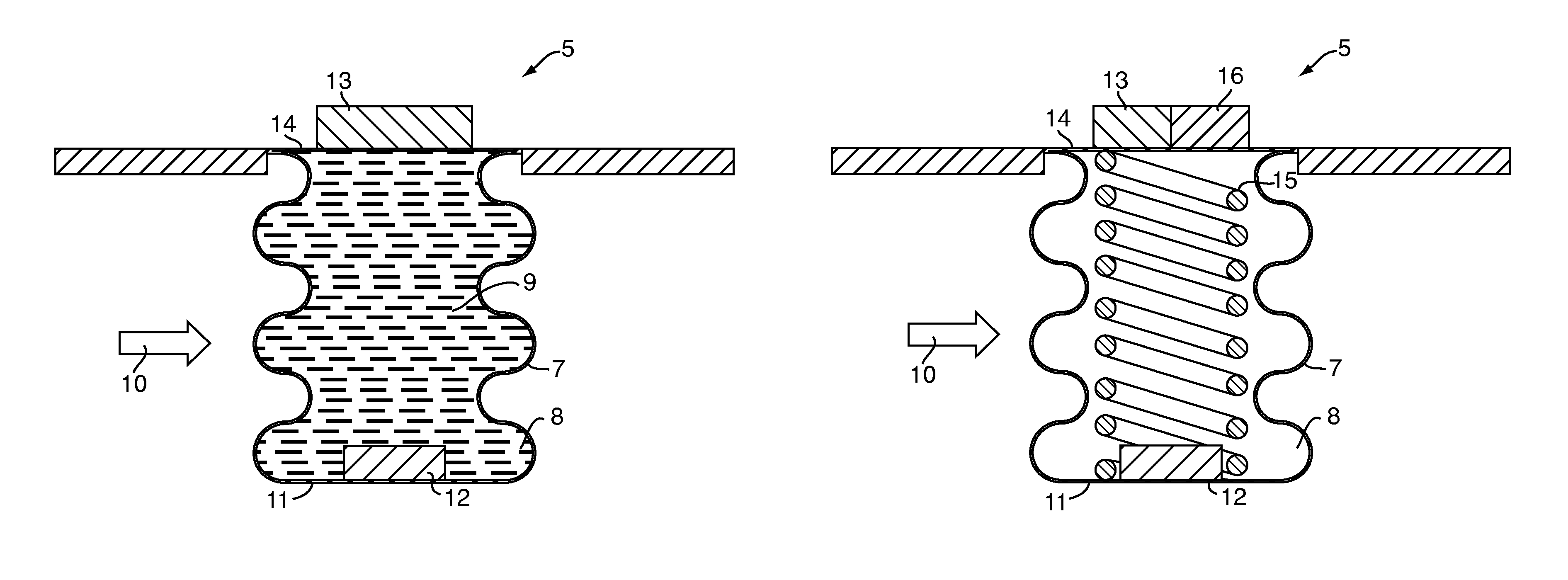
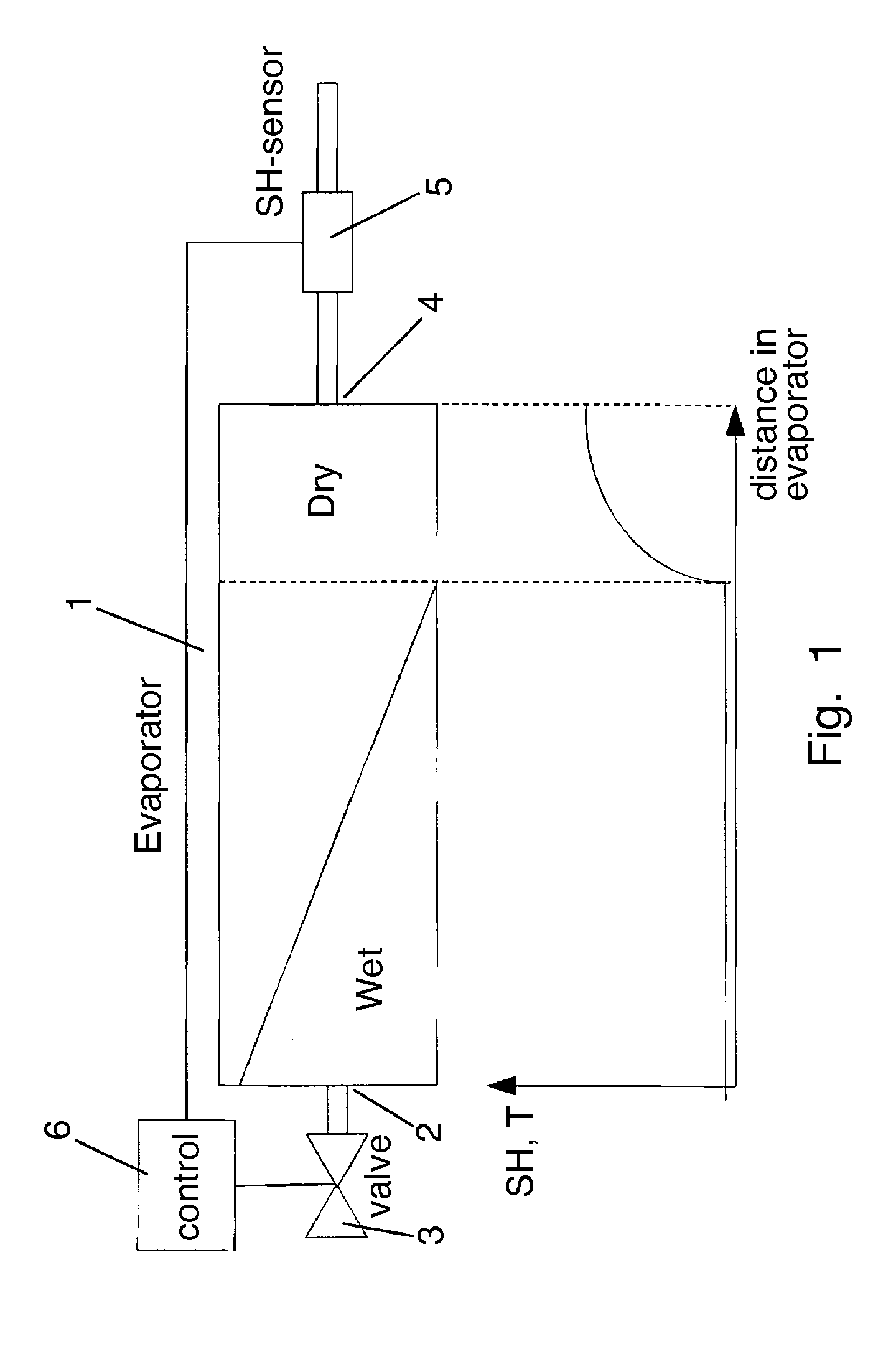
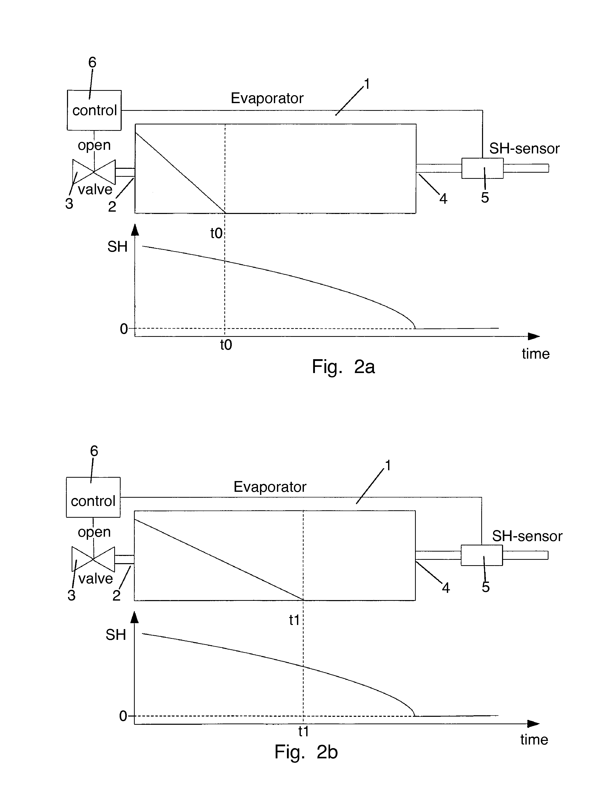
[0044]FIG. 1 is a schematic view of an evaporator 1 arranged in a refrigeration path of a refrigeration system. The evaporator 1 comprises an inlet 2 which is fluidly connected to an expansion valve 3. The opening degree of the expansion valve 3 determines the supply of refrigerant to the evaporator 1. The evaporator 1 further comprises an outlet 4 which is fluidly connected to a superheat sensor 5.

[0045]The superheat sensor 5 measures one or more parameters which is / are relevant to the superheat of the refrigerant leaving the evaporator 1 via the outlet 4. The superheat sensor 5 may measure corresponding values of the temperature and the pressure of the refrigerant leaving the evaporator 1. Alternatively, the superheat sensor 5 may be adapted to measure a single parameter which is representative for the superheat of the refrigerant leaving the evaporator 1.

[0046]The superheat sensor 5 supplies the result of such measurements to a control unit 6. Based on the received results the co...


PUM

PropertyMeasurementUnit
rotational speedaaaaaaaaaa
temperatureaaaaaaaaaa
pressureaaaaaaaaaa

Abstract

A method for calibrating a superheat sensor (5) for a refrigeration system is provided. The method comprises the following steps. Increasing an amount of liquid refrigerant in the evaporator (1), e.g. by increasing an opening degree of the expansion valve (3). Monitoring one or more parameters, e.g. the temperature of refrigerant leaving the evaporator (1), said parameters reflecting a superheat value of the refrigerant. Allowing the value of each of the parameter(s) to decrease. When the value(s) of the monitored parameter(s) reaches a substantially constant level, defining the superheat value corresponding to the constant level to be SH=0. The superheat sensor (5) is then calibrated in accordance with the defined SH=0 level. When the parameter(s) reaches the substantially constant level it is an indication that liquid refrigerant is allowed to pass through the evaporator (1), and thereby that the superheat of the refrigerant leaving the evaporator (1) is zero. Calibration can be performed on site, and it is therefore not necessary to calibrate the sensor (5) at the manufacturing facility. Thereby it is no longer required to match calibration information with a specific sensor.

Description

CROSS REFERENCE TO RELATED APPLICATIONS[0001]This application is entitled to the benefit of and incorporates by reference essential subject matter disclosed in International Patent Application No. PCT / DK2009 / 000198 filed on Sep. 4, 2009, Danish Patent Application No. PA 2008 01236 filed on Sep. 5, 2008.FIELD OF THE INVENTION[0002]The present invention relates to a method for calibrating a superheat sensor for a refrigeration system. The superheat sensor being calibrated may advantageously be arranged in a refrigerant path of a refrigeration system, further having an expansion valve, an evaporator and a compressor arranged therein.BACKGROUND OF THE INVENTION[0003]Refrigeration systems are often operated by adjusting a degree of opening of an expansion valve and / or by opening / closing an expansion valve, thereby controlling the amount of liquid refrigerant being supplied to an evaporator. It is desirable to control the expansion valve in such a manner that it is obtained that all of th...

Claims


Application Information

Patent Timeline
Patent Type & Authority Patents(United States)
IPC IPC(8): G01K13/02F25B41/06F25B49/00
CPCF25B41/062F25B49/005F25B2600/21F25B2700/21175F25B41/34Y02B30/70
Inventor VONSILD, ASBJOERN LETHTHYBO, CLAUSLARSEN, LARS FINN SLOTHSPANGBERG, JAKOBHOEYER, JESPERVOGLER, JES
Owner DANFOSS AS
Why Eureka
Try Eureka