
Fan blade and attaching means therefor

a technology of attaching means and blades, which is applied in the direction of propellers, propulsive elements, water-acting propulsive elements, etc., can solve the problems of limited usability at temperatures above approx, aluminum blades made of special aluminum alloys, such as sand-casting alloys, and inability to substantially improve this inadequacy. , to achieve the effect of saving weight and high tensile strength

Active Publication Date: 2014-09-09
W & S MANAGEMENT
View PDF6 Cites 15 Cited by
  • Summary
  • Abstract
  • Description
  • Claims
  • Application Information

AI Technical Summary

Benefits of technology

This patent is about attaching means for attaching a blade section of a fan blade to a fan hub, which can withstand high temperatures and rotational speeds. The attaching means are separate from the fan blade and can be made from a high-tensile strength material, while the fan blade can be made from a lightweight material that still maintains necessary strength. This helps to save weight and reduces costs, making it suitable for individual production. The blade section can also be made from a material with a lower density compared to steel, such as aluminum, to keep the fan lightweight without sacrificing strength.

Problems solved by technology

However, the disadvantage of fan blades made of aluminum is their limited usability at temperatures above approx.
Even special aluminum alloys, such as sand-casting alloy, cannot substantially improve this inadequacy.
As a result of this disadvantageous property of aluminum, fan blades produced of cast aluminum can be detached from the hub at high temperatures, such as can occur in the event of fires.
However, fans with solid cast steel blades are disadvantageously very heavy.
To this end the two hub bodies must be present disadvantageously as cast parts or they must be embodied expensively as a welded construction.
This is unfavorable in particular with the individual production of large fans or with small batches.

Method used


Image

  • Fan blade and attaching means therefor
  • Fan blade and attaching means therefor
  • Fan blade and attaching means therefor

Examples


Embodiment Construction

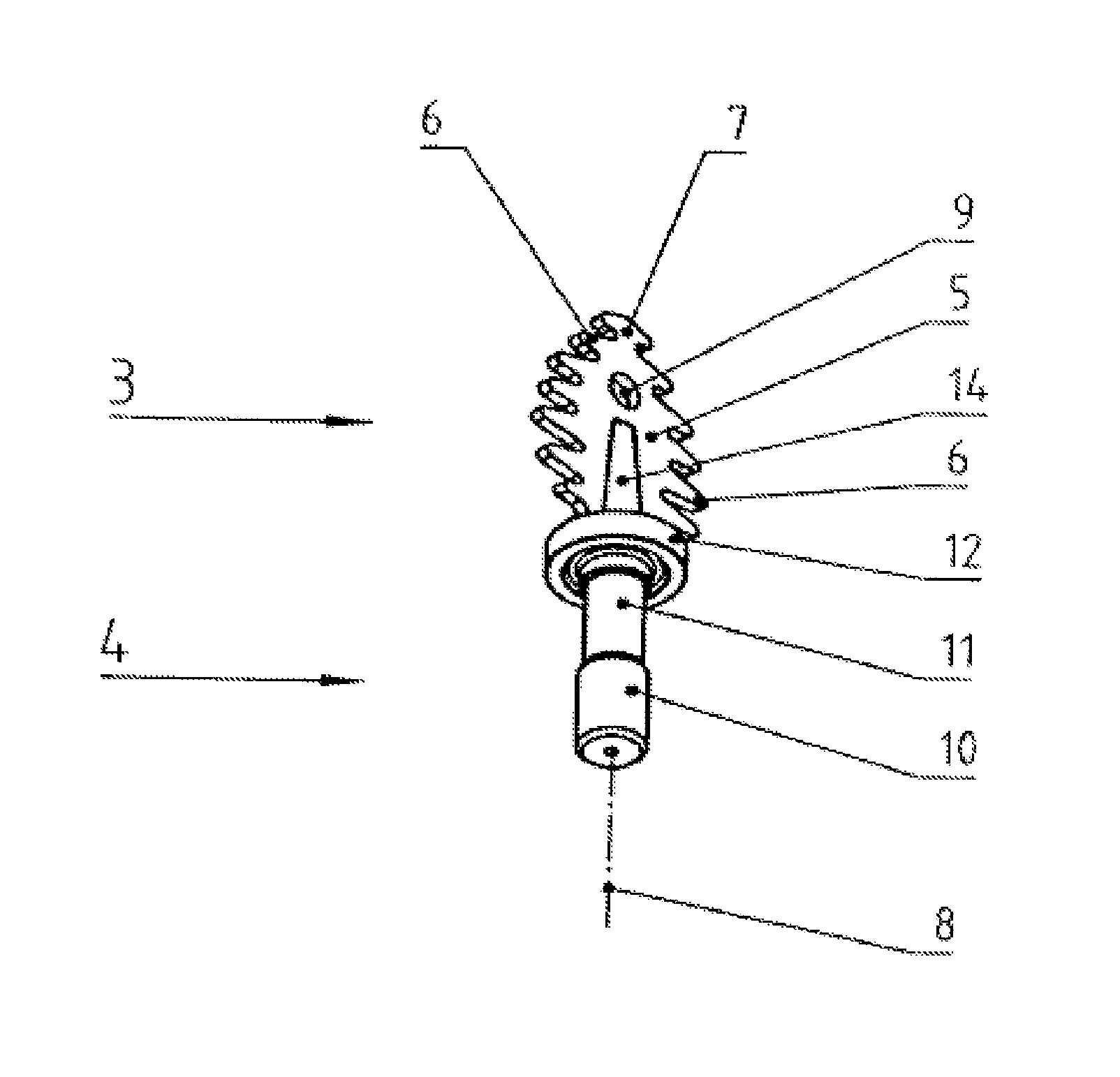
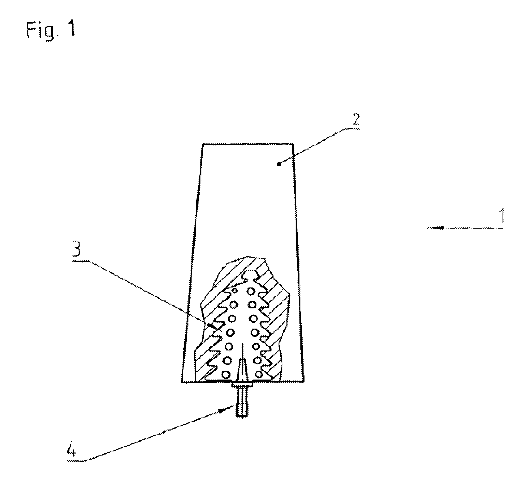
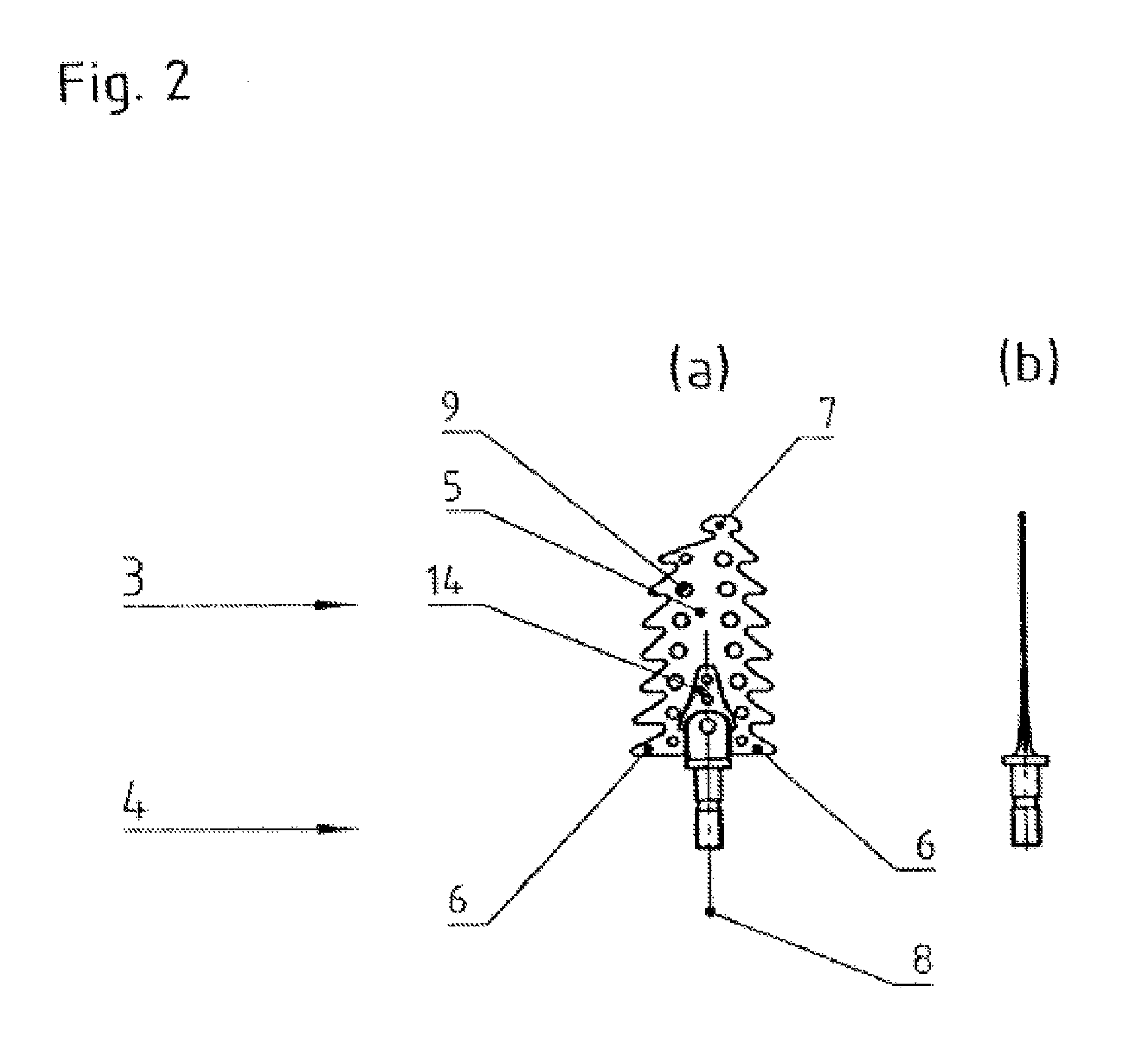
[0042]The figure shows diagrammatically in a plan view a fan blade 1 with a blade section 2 and an attaching part 3. The representation is a partial elevation drawing. In the following radial direction always means a radial direction based on a fan blade, corresponding to a longitudinal axis of the blade section 2 in FIG. 1. Likewise, axial direction means the axial direction of the complete fan. FIG. 1 therefore shows that the attaching part 3 is located in the interior of the solid blade section 2. To produce the fan blade 1, the attaching part 3 is cast with the blade section 2 during the casting of the blade section 2.

[0043]The attaching part 3 is cast with the blade section 2 such that a base section 4 projects out of the radial inner front face of the blade section 2. With base section 4, the fan blade 1 is usually inserted into a fan hub (not shown) and fixed there. In the exemplary embodiment the blade section 2 of the fan blade 1 is essentially composed of aluminum. On the ...


PUM

PropertyMeasurementUnit
temperaturesaaaaaaaaaa
temperatureaaaaaaaaaa

Abstract

In order to disclose attaching means (3) for attaching a blade section (2) of a fan blade (1), in particular of a smoke extractor fan, to a fan hub, as well as a fan blade (1), which guarantee a high tensile strength even at high temperatures, wherein the attaching means (3) and fan blades (1) are to be produced so as to save as much weight as possible, it is proposed that the attaching means (3) have a connecting section (5) embodied to produce a high-tensile connection to a blade section (2) of a fan blade (1), which connecting section can be arranged essentially in the interior of the blade section (2).

Description

CROSS REFERENCE TO RELATED APPLICATIONS[0001]This application is the National Phase Application under 35 USC §371 of International Application No. PCT / EP2010 / 001186, filed Feb. 26, 2010, which claims priority to German Patent Application 10 2009 010 748.7, filed Feb. 26, 2009.BACKGROUND[0002]A. Technical Field[0003]The present invention relates to attaching means for attaching a blade section of a fan blade, in particular of a smoke extractor fan, to a fan hub.[0004]The invention also relates to a fan blade, in particular for smoke extractor fans, with attaching means for attaching the fan blade to a fan hub and with a blade section.[0005]B. Background of the Invention[0006]Fans for subways or tunnels and / or closed vehicle buildings, such as underground parking garages, for example, must operate reliably for extremely long service lives with a variety of load and ambient conditions. Typically, the installation of fans in subways, tunnels or underground parking garages is designed fo...

Claims


Application Information

Patent Timeline
Patent Type & Authority Patents(United States)
IPC IPC(8): F04D29/36F04D29/02F04D29/38
CPCF04D29/023F04D29/388F04D29/64F04D29/34F05D2300/171F05D2230/64F04D29/322F04D29/38F04D29/646
Inventor WITT, HENRIK
Owner W & S MANAGEMENT
Learn More