Method for minimizing emissions while forming a polyurethane foam

a technology of polyisocyanate and emissions, which is applied in the direction of superimposed coating process, liquid/solution decomposition chemical coating, manufacturing tools, etc., can solve the problems of generating potentially dangerous emissions, requiring respirators, eye, skin and respiratory system irritation, etc., and achieves the effect of minimizing emissions of polyisocyana

Active Publication Date: 2014-09-09
BASF AG
View PDF27 Cites 8 Cited by
  • Summary
  • Abstract
  • Description
  • Claims
  • Application Information

AI Technical Summary

Benefits of technology

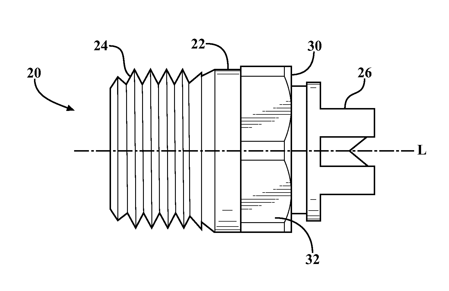
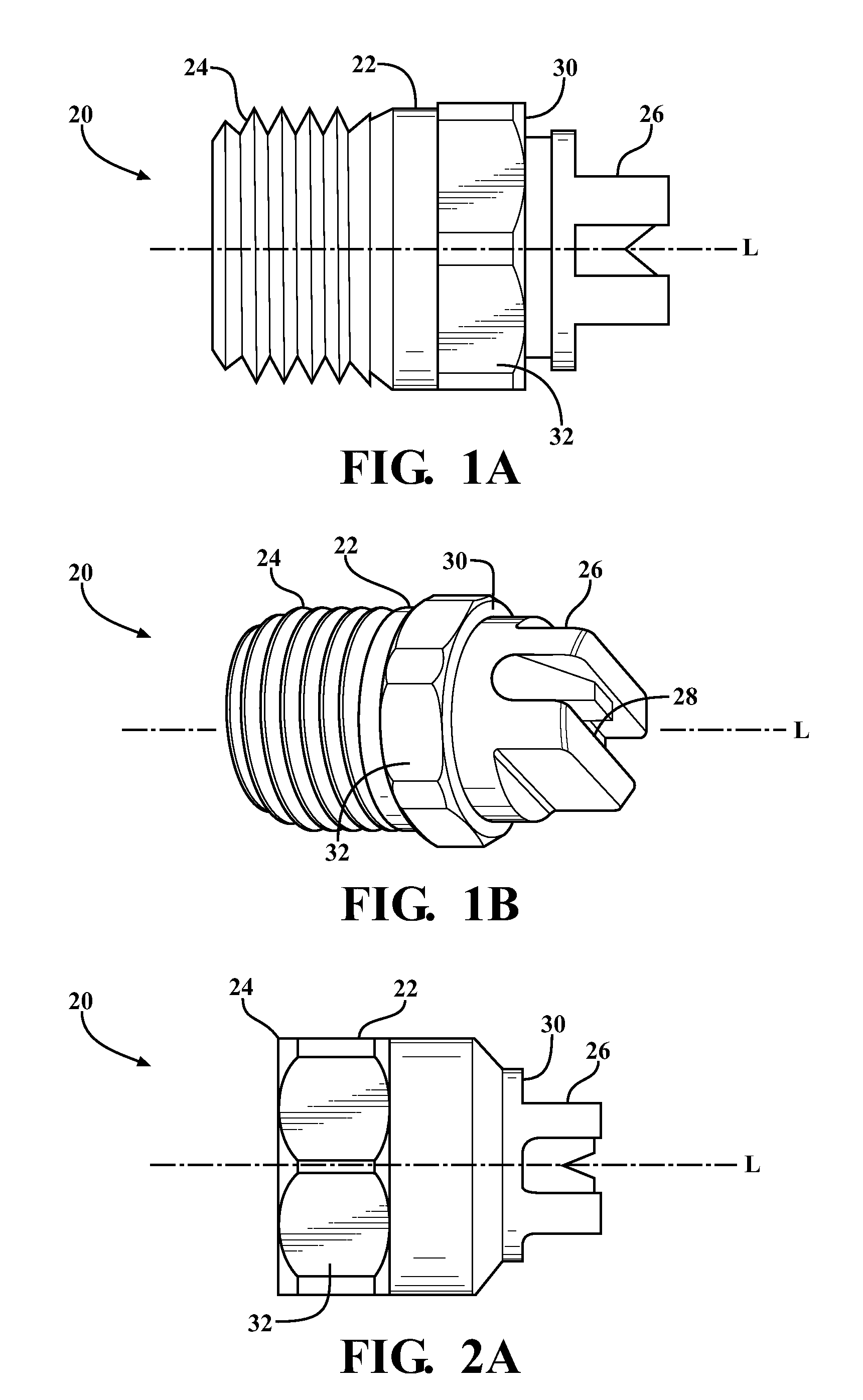
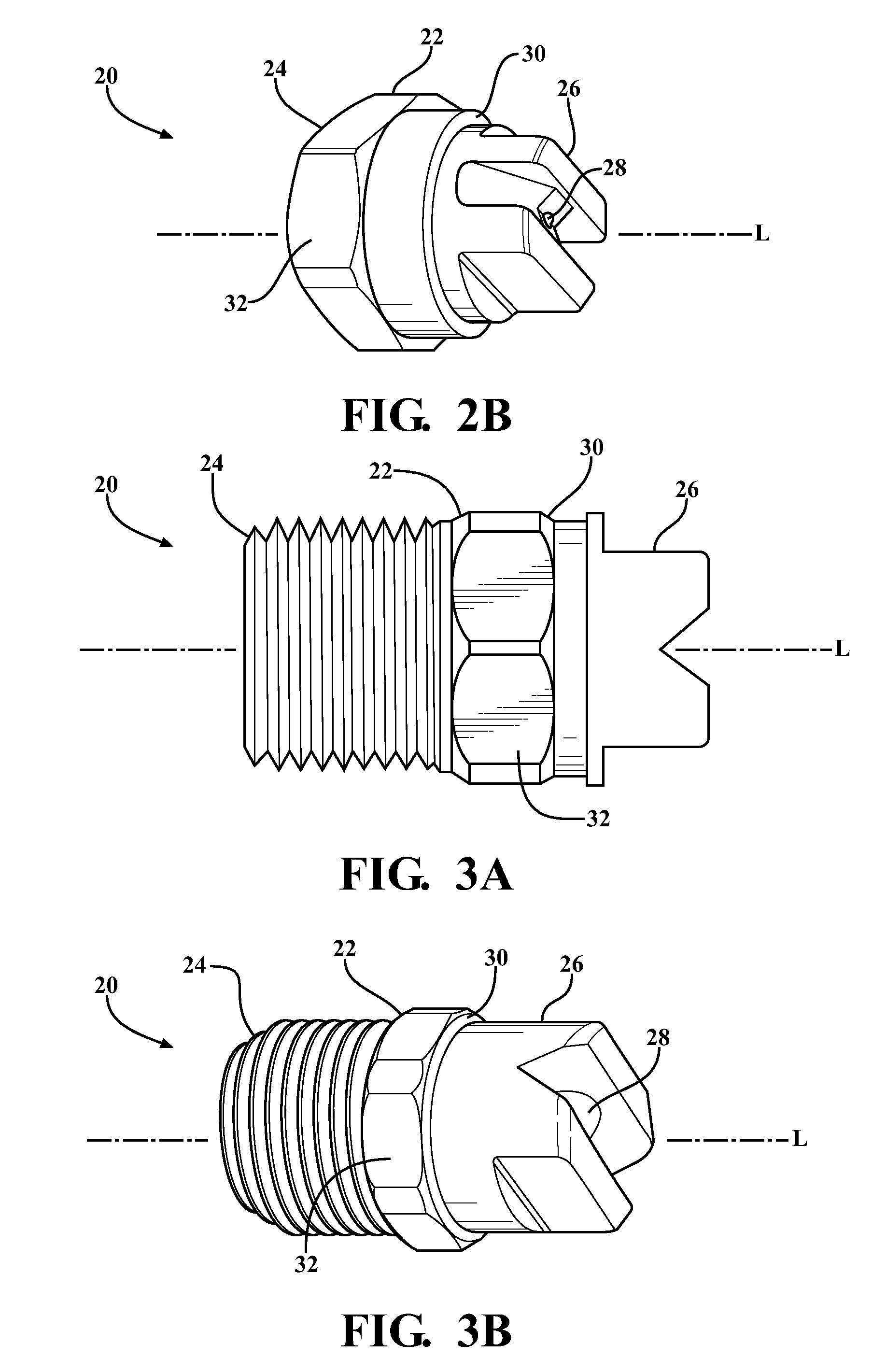
[0006]The instant invention provides a method for minimizing emissions of a polyisocyanate while spraying a mixture of a resin composition and the polyisocyanate onto a surface. The resin composition has a hydroxyl content of at least 400 mg KOH / g and includes (i) a blowing agent that is a liquid under a pressure greater than atmospheric pressure, (ii) a first polyol selected from the group of a Mannich polyol, an autocatalytic polyol, and combinations thereof, (iii) at least one additional polyol other than (ii) the first polyol, (iv) an catalyst, (v) an surfactant, and (vi) optionally water. The method includes the steps of providing the polyisocyanate and providing the resin composition. The method also includes the step of combining the resin composition with the polyisocyanate in the absence of other blowing agents to form the mixture and the step of spraying the mixture onto the surface to form a polyurethane foam having a closed cell content of at least 90 percent thereon. The mixture is sprayed through a spray nozzle at a spray angle corresponding to a control spray angle of from 15 to 125 degrees measured at a pressure of from 10 to 40 psi using water as a standard. The step of spraying produces less than 50 parts of the polyisocyanate per one billion parts of air according to OSHA Method 47.
[0007]The instant invention also provides a polyurethane spraying system used to minimize emissions of the polyisocyanate while spraying the mixture onto the surface. The system includes a first reactant supply tank including the resin composition and a second reactant supply tank including the polyisocyanate. The system also includes a source of a gaseous propellant that is coupled with the first and second reactant supply tanks. The system further includes a mixing apparatus that is coupled with the first and second reactant supply tanks for mixing the resin composition and the polyisocyanate prior to spraying. Still further, the system includes a spray nozzle that is coupled with the mixing apparatus and that minimizes emissions of the polyisocyanate while the mixture is sprayed onto the surface.
[0009]The polyisocyanate and the resin composition of this invention react to form a polyurethane foam that cures faster than conventional sprayed foams and that has a minimized ozone depleting potential, thus increasing environmental friendliness. The spray nozzle used to spray the mixture of the polyisocyanate and the resin composition minimizes emissions of the polyisocyanate generated by spraying the mixture and allows the mixture to be sprayed in closed and / or non-ventilated environments with minimized risk of over exposure to the polyisocyanate. The spray nozzle and method of this invention also minimize a need to use respirators and protective equipment when spraying the mixture due to the minimized emissions of the polyisocyanate. Furthermore, the spray nozzle also allows for effective and efficient distribution of the mixture thereby reducing overspray and waste.

Problems solved by technology

However, to form these closed cell foams and utilize the sprayable froth polyurethane systems, polyisocyanates and polyols must be sprayed onto surfaces, thereby generating potentially dangerous emissions.
Polyisocyanates are believed to cause irritation and sensitization of eyes, skin, and respiratory systems upon contact and with repeated exposure.
Typical sprayable froth polyurethane systems produce amounts of polyisocyanates in the air that exceed both the established PELs and TLVs thus requiring use of respirators, expensive engineering controls, and other protective equipment.

Method used


Image

  • Method for minimizing emissions while forming a polyurethane foam
  • Method for minimizing emissions while forming a polyurethane foam
  • Method for minimizing emissions while forming a polyurethane foam

Examples


examples

[0092]A mixture (Mixture 1) of a polyisocyanate and a resin composition of this invention is formed and is sprayed onto a surface according to the method of this invention. A comparative mixture (Comparative Mixture 1) including the same polyisocyanate and a comparative resin composition is also formed and sprayed onto a surface but not according to this invention. During spraying, concentrations (i.e., emissions) of the polyisocyanate in the air are measured according to OSHA Method 47 and reported below.

Formation and Spraying of Mixture 1:

[0093]The chemical composition of Mixture 1 is as follows:

Polyisocyanate:

[0094]The Polyisocyanate is methylene diphenyl diisocyanate (MDI) that is commercially available from BASF Corporation. The Polyisocyanate is combined with the Resin Composition described below at an Isocyanate Index of about 115.

Resin Composition:

[0095]The Resin Composition includes the following wherein the parts by weight are per 100 parts by weight of the Resin Compositi...


PUM

PropertyMeasurementUnit
pressureaaaaaaaaaa
radiusaaaaaaaaaa
pressureaaaaaaaaaa

Abstract

A method minimizes emissions while spraying a mixture of a resin composition and a polyisocyanate onto a surface. The resin composition has a hydroxyl content of at least 400 mg KOH / g and includes a blowing agent that is a liquid under pressure, a first polyol, at least one additional polyol other than the first polyol, and optionally a catalyst, surfactant, and water. The mixture is sprayed onto the surface to form a polyurethane foam having a closed cell content of at least 90 percent. The mixture is also sprayed through a spray nozzle at a spray angle corresponding to a control spray angle of from 15 to 125 degrees measured at a pressure of from 10 to 40 psi using water as a standard. The step of spraying produces less than 50 parts of the polyisocyanate per one billion parts of air according to OSHA Method 47.

Description

CROSS-REFERENCE TO RELATED APPLICATIONS[0001]The subject patent application claims priority to and all the benefits of U.S. Provisional Patent Application Ser. No. 61 / 240,513 which was filed on Sep. 8, 2009, the entire specification of which is expressly incorporated herein by reference.FIELD OF THE INVENTION[0002]The present invention generally relates to a method for minimizing emissions while spraying a mixture of a polyisocyanate and a resin composition onto a surface to form a polyurethane foam thereon. More specifically, the method includes spraying the mixture through a spray nozzle at a particular spray angle and pressure to form the polyurethane foam.DESCRIPTION OF THE RELATED ART[0003]It is well known in the art that various hydrofluorocarbons have been investigated as blowing agents for polyurethane based foams due to their low ozone depletion potentials. Some hydrofluorocarbon are used in sprayable polyurethane systems to form closed cell polyurethane foams that exhibit ...

Claims


Application Information

Patent Timeline
Patent Type & Authority Patents(United States)
IPC IPC(8): B05D1/02
CPCB05B7/0075C08G18/4018C08G18/4883C08J2375/04B29B7/805B05B1/02B05B1/06B29B7/325C08G2101/0025B05B7/0031C08G18/4208B05B7/26C08G2150/60C08J2201/022B29B7/7404B05B7/1693C09D175/08B05B1/042C08G2150/50C08G18/5033C08J9/14C08G2110/0025B05C5/02
Inventor OGONOWSKI, JOSEPH
Owner BASF AG
Why Eureka
Try Eureka