LED lighting circuit

a technology of led lighting and circuits, which is applied in the direction of electroluminescent light sources, light sources, electrical equipment, etc., can solve the problems of reducing the lifetime affecting the operation of the ac-led chip, and exhibiting unacceptably high optical flicker

Inactive Publication Date: 2014-09-09
KONINK PHILIPS ELECTRONICS NV
View PDF12 Cites 11 Cited by
  • Summary
  • Abstract
  • Description
  • Claims
  • Application Information

AI Technical Summary

Benefits of technology

[0018]An advantage of the AC-LED lighting device according to the invention is that it can easily be designed to be used as a ‘retro-fit’ device, for example as a ‘light bulb’ to be used as a low-energy replacement for an incandescent or halogen lamp with any standard light fitting. A consumer can therefore purchase such an AC-LED lighting device and use it for an existing luminaire or lighting fixture in the same manner as a conventional light bulb.
[0028]The polarity controller effectively imposes or establishes the polarity to be used in driving the AC-LED chip. Seen another way, the polarity controller effectively determines which string of LEDs is driven, and can reverse the polarity at any suitable time, for example according to some random event. Therefore, in a preferred embodiment of the invention, the polarity controller is realized to control the polarity of the polarity-selectable DC signal applied to the AC-LED arrangement according to a random initial condition arising upon connection of the AC-LED lighting circuit to the AC power supply. In a particularly simple approach, the polarity of the AC input voltage at the instant of connection of the AC-LED lighting circuit to the mains supply can be used to set the polarity that is to be applied to the AC-LED chip. The polarity of the AC input voltage can easily be determined using off-the-shelf circuit components, as will be known to the skilled person.
[0031]In the solution described above, the polarity is reversed whenever the lighting device is connected to the mains supply, for example when a corresponding light switch is activated by a person. In an alternative approach, the polarity can be reversed even during operation of the lighting device, i.e. when the lighting device is turned on. This may be done, for example, to prevent one set or string of LEDs from being stressed for an excessively long period of time.
[0036]As mentioned above, other measurable parameters such as temperature can be taken into account when determining a suitable switch-over from one string to the other. For example, in a further preferred embodiment, a temperature measurement means can supply the polarity controller with ambient temperature values measured in the vicinity of the AC-LED arrangement. When the temperature is close to the normal room temperature, the accumulation of time is done at a first (normal) rate. When the ambient temperature measured in the vicinity of the AC-LED is higher than normal room temperature, however, the accumulation of time is preferably done at a second, faster, rate. The accumulated time value during the operation of each one of the sets of LEDs is therefore a function of the temperature, so that, if one of the LED strings is known to age faster when operated at high temperatures than the other string, the accumulation rate for this string t at higher temperatures is faster than that for the other string. In this way, operation at higher temperatures will result in an earlier reversal of the voltage, so that the faster ageing of this set of LEDs during operation at higher temperature is to some extent compensated by the reduced operation time of this set of LEDs.
[0037]In order to prevent visible artifacts when the polarity is reversed during operation of the lamp, the polarity reversal preferably takes place within a very short time, effectively faster than the transient during the zero crossing of the mains voltage when the AC-LED lighting circuit is used with an AC mains power supply. Such brief transition times ensure little or no visible effect on the light output by the device, particularly when the polarity is reversed during operation. To compensate for a possible ‘dip’ or ‘step’ in the light output due to a transition between strings, the amplitude of the drive signal to the AC-LED arrangement can be slightly increased just before and just after the transition process. Alternatively, a kind of pulse-width modulation could be applied during the transition from the previously active string to the string that was previously inactive. Over a certain period of time, for example a “take-over interval” of one minute, the strings can be alternately driven so that the previously active string is driven for progressively shorter lengths of time while the previously inactive string is driven for corresponding progressively longer durations until the string that was previously inactive is continually driven, and the previously active string is now off. In this way, a possible visible artifact which might arise from small physical differences between the strings (for example a slight difference in dominant wavelength due to small temperature differences among the strings) can be rendered unnoticeable.
[0039]When the AC-LED lighting circuit according to the invention is to be realized in a device that is directly connectable to the mains supply, it preferably comprises a power supply connector for connecting the AC-LED lighting circuit to an outlet of an AC power supply. Such a connector can be any suitable connector such as an Edison connector, a bayonet connector, a bipin connector, etc., in a standard design. For example, a standard Edison E27 or E14 connector could preferably be used, so that the AC-LED lighting circuit according to the invention can easily be used as a retro-fit solution for use in existing lighting fixtures. Evidently, a switch may also be used to actually make or break the circuit of which the AC-LED lighting device is a part. Therefore, in the following, the expression “connection of the AC-LED lighting circuit to the AC power supply” can mean the act of connecting the AC-LED lighting circuit to a mains outlet, or the act of closing a switch.

Problems solved by technology

However, the light produced by AC-LEDs driven from the AC mains supply can exhibit an unacceptably high degree of optical flicker, caused by the rapid alteration in polarity at mains frequency.
This flicker can be irritating, particularly in the case of indoor lighting applications.
However, in this mode of operation, only one part of the AC-LED chip is continually driven with a forward current, while the other part is continually exposed to a reverse bias voltage and is effectively not used.
Apart from the poor utilization, this mode of operation leads to a reduction in lifetime of the AC-LED chip, because, when driven continually with a DC signal, only one of the two strings of LEDs is continually ‘stressed’ with a drive signal to generate light.

Method used


Image

  • LED lighting circuit
  • LED lighting circuit
  • LED lighting circuit

Examples


Embodiment Construction

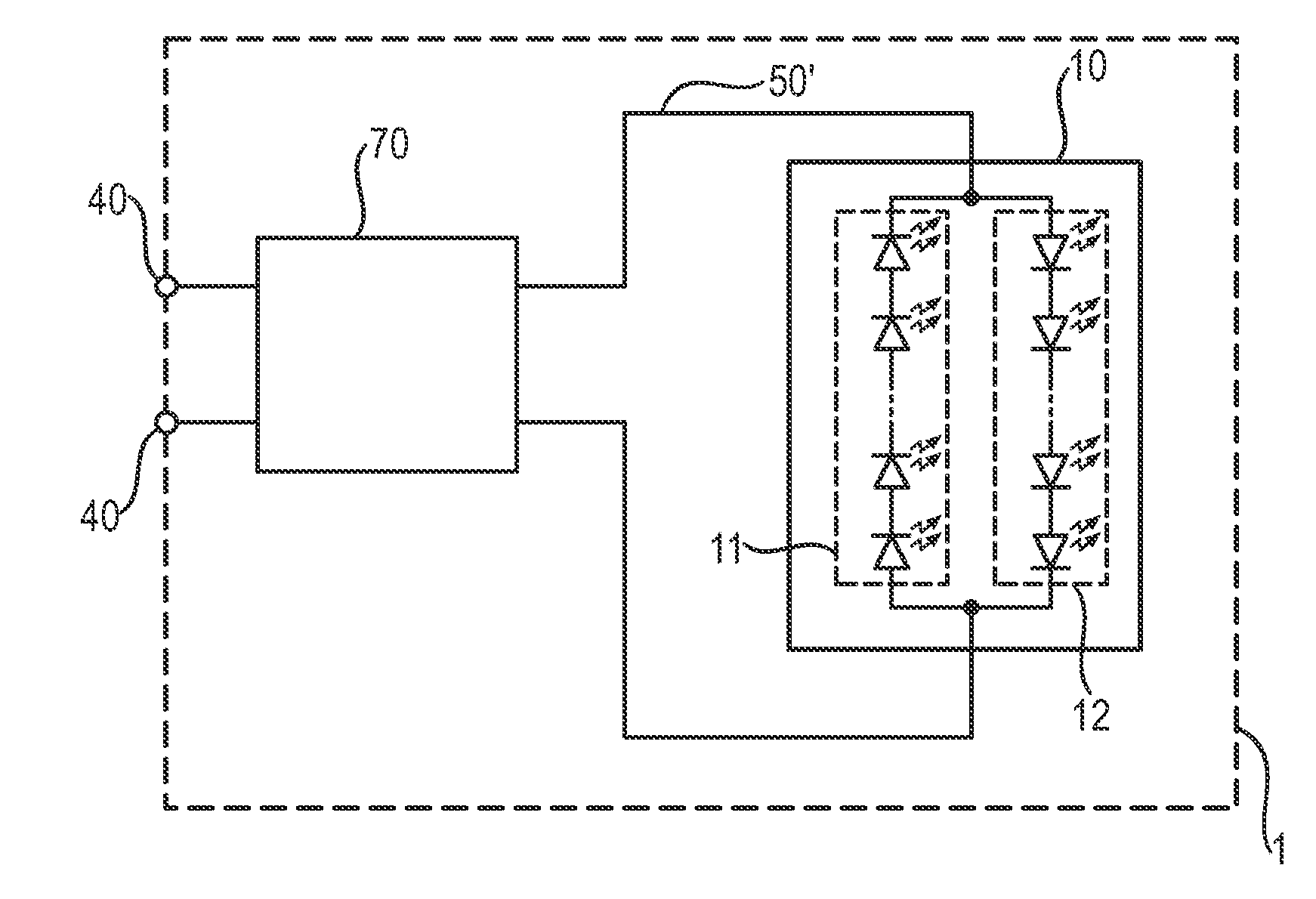
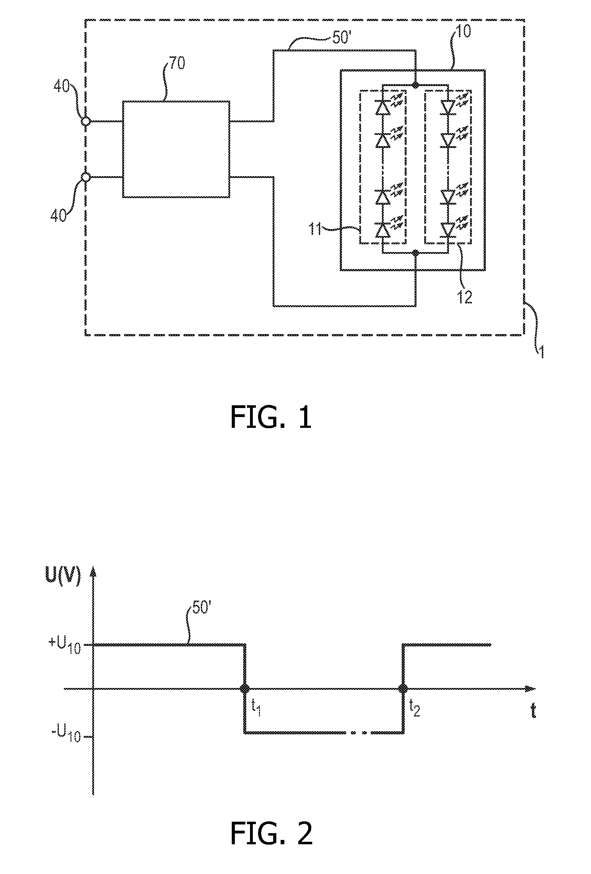
[0049]FIG. 1 shows a simplified circuit diagram in which an AC-LED lighting circuit 1 can be connected, by means of suitable connectors 40, to a DC power supply of constant or fixed polarity. A polarity controller 70 uses the fixed-polarity DC signal to derive or generate a polarity-selectable DC signal 50′ which toggles as required between positive and negative polarity and which is applied to an AC-LED arrangement 10. The AC-LED arrangement 10 essentially comprises two strings 11, 12 of LEDs (represented by the standard circuit symbol), connected inverse parallel so that, for an applied potential, one string conducts while the other string is reverse biased. Of course, as the skilled person will appreciate, the AC-LED arrangement 10 can comprise several chips connected in series or in parallel, depending on the desired light output, and any of these chips can comprise more than two strings.

[0050]FIG. 2 shows an idealized voltage 50′ applied to the AC-LED arrangement 10 of FIG. 1. ...


PUM


Abstract

The invention describes an AC-LED lighting circuit (1) comprising an AC-LED arrangement (10) with at least a first set (11) of LEDs connected according to a first polarity and a second set (12) of LEDs connected according to the opposite polarity, which AC-LED lighting circuit (1) is characterized by (i) a source (61) of a polarity-selectable DC input signal (51) to be applied to the AC-LED arrangement (10), or a connecting means (40) for connecting the AC-LED lighting circuit (1) to a fixed-polarity DC input signal (50) and a conversion means (T1, T2, T3, T4) for converting the fixed-polarity DC input signal (50) to a polarity-selectable DC signal (50′) to be applied to the AC-LED arrangement (10); and (ii) a polarity controller (70, 71) realized to control the polarity of the polarity-selectable DC signal (50′, 51) applied to the AC-LED arrangement (10) such that the first set (11) of LEDs of the AC-LED arrangement (10) is driven when the polarity-selectable DC signal (50′, 51) has the first polarity, and the second set (12) of LEDs of the AC-LED arrangement (10) is driven when the polarity-selectable DC signal (50′, 51) has the opposite polarity. The invention further describes an AC-LED lighting device (9) comprising such an AC-LED lighting circuit (1) and having an outer chamber (90) enclosing the AC-LED arrangement (10) of the AC-LED lighting circuit (1) and a lamp base (91) at least partially incorporating the connector (3) of the AC-LED lighting circuit (1). The invention also describes a method of driving an AC-LED lighting circuit comprising an AC-LED arrangement (10).

Description

FIELD OF THE INVENTION[0001]The invention describes an LED lighting circuit, an AC-LED lighting device and a method of driving an LED lighting circuit.BACKGROUND OF THE INVENTION[0002]In lighting solutions, LEDs (light-emitting diodes) are playing an ever greater role, made possible by the advances in LED technology in recent years. LED lighting arrangements can be designed to emit white light, necessary for indoor and outdoor illumination purposes, by combining red, green and blue LEDs in solid-state lighting (SSL) solutions. Some LEDs can be coated with phosphor to convert the emitted light into another colour, for example blue ‘pump’ light can be converted into yellow, green or red light. Such coated LEDs can be combined with non-coated LEDs in an arrangement to give white light. Typically, phosphor-converted white-emitting LEDs are obtained by a combination of phosphor-converted yellowish light and some part of the blue pump light. The development of LEDs with a high light outpu...

Claims


Application Information

Patent Timeline
Patent Type & Authority Patents(United States)
IPC IPC(8): H05B41/16H05B37/00H05B39/00H05B41/24H05B41/00H05B41/14H05B44/00
CPCH05B33/0815H05B33/0803H05B45/37
Inventor RADERMACHER, HARALD, JOSEF, GUNTHER
Owner KONINK PHILIPS ELECTRONICS NV
Why Eureka
Try Eureka