
Airborne radar jamming system

a radar and airborne technology, applied in the field of signal jamming systems, can solve the problem that tracking radar using signal integration techniques cannot resolve the radar return signal

Active Publication Date: 2014-09-09
THE BOEING CO
View PDF12 Cites 237 Cited by
  • Summary
  • Abstract
  • Description
  • Claims
  • Application Information

AI Technical Summary

Benefits of technology

This patent describes a method and system for jamming radar signals using an anti-signal-integration method. The system includes a device that generates a noise signal and transmits it along a transmission line to a drogue radiator that radiates the noise signal away from the aircraft. The system also includes an anti-integration network that generates a noise signal with a gap to hide the energy of the reflected radar signals. The technical effect of this invention is that it prevents the radar signals from being integrated with the jamming signals, making it difficult for the tracking radar to detect and locate the aircraft.

Problems solved by technology

By so doing, tracking radar using signal integration techniques cannot resolve the radar return signal which would otherwise be superposed as a signal energy “bump” on a constant level background of the jamming noise signal.

Method used


Image

  • Airborne radar jamming system
  • Airborne radar jamming system
  • Airborne radar jamming system

Examples


Embodiment Construction

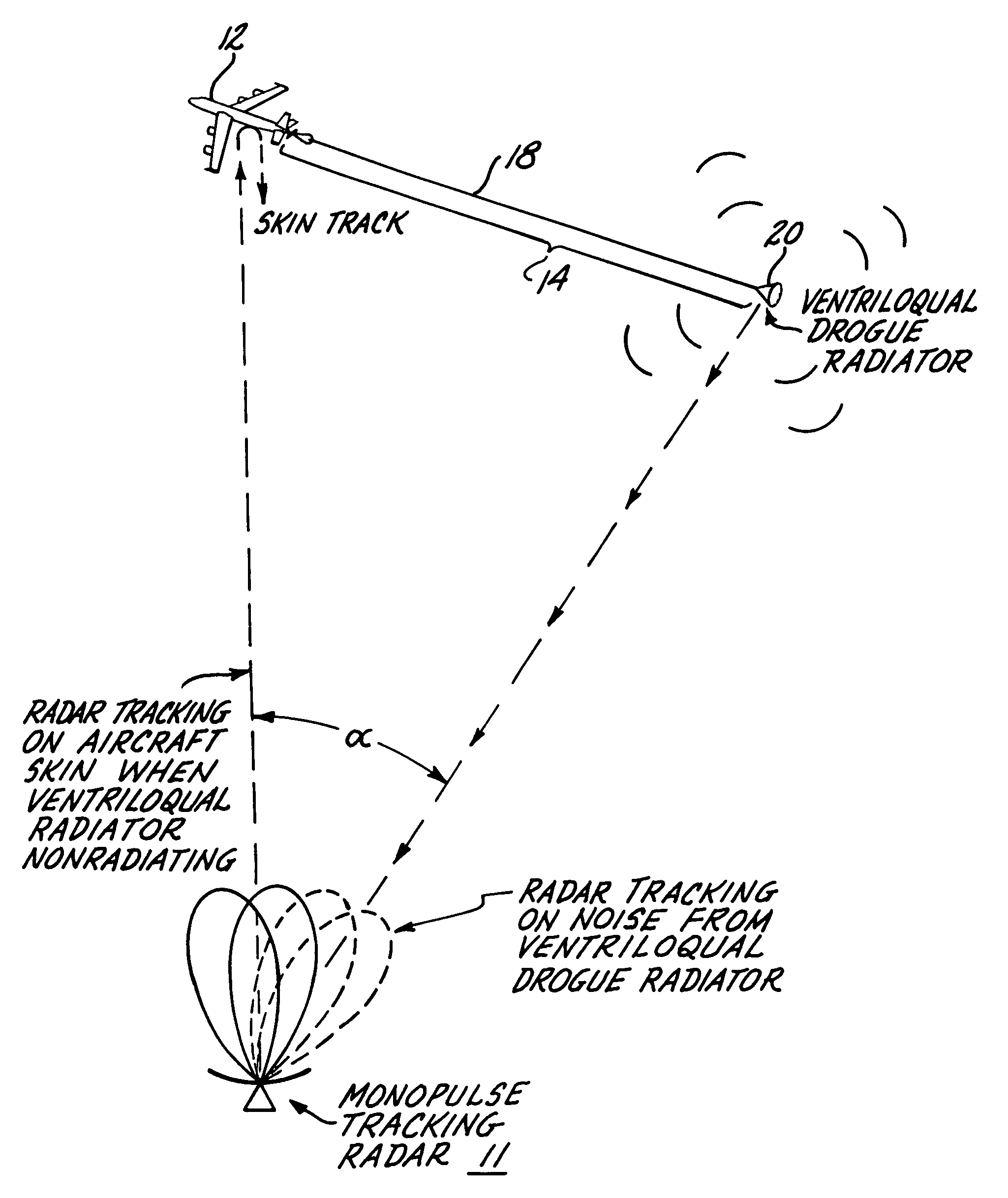
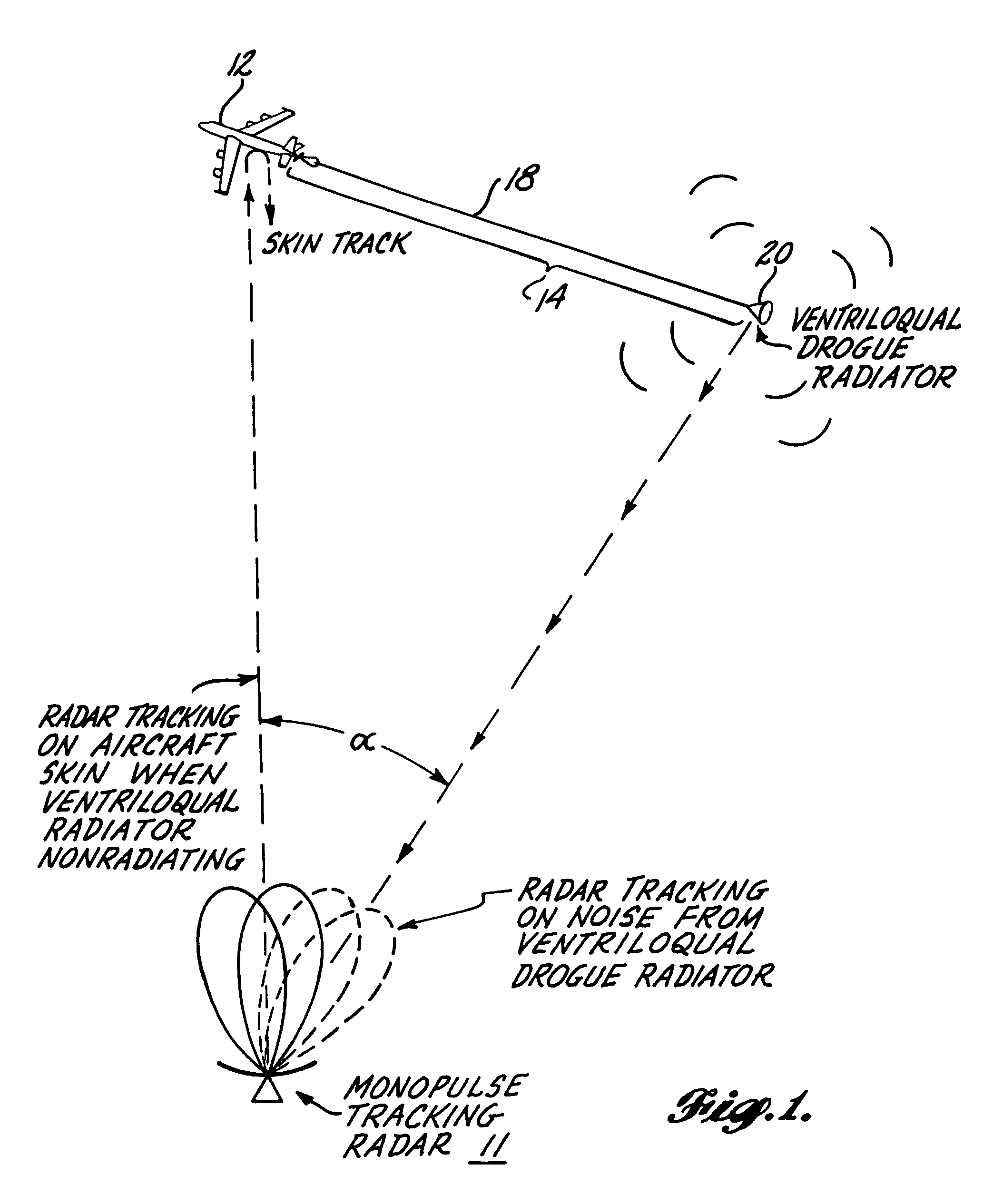
[0017]FIG. 1 illustrates how the ventriloqual-like jamming system radiates a radar jamming noise signal in a manner that denies radar 11, angle information of the position of a target aircraft 12, even though the signal receiving components of radar 11 are capable of homing on and tracking a noise source when the skin-reflected radar return signal is masked by radiating a jamming signal. Attached to aircraft 12 so as to be towed thereby is a single wire transmission line subsystem 14 including a wave launcher 16, a single wire transmission line 18 extending from a leading end which is mechanically and electrically coupled to the towing aircraft 12 by wave launcher 16. Line 18 terminates at a substantial distance behind aircraft 12, and a drogue radiator 20 is attached to the trailing end of the line.

[0018]As described in greater detail in the section herein dealing with the system's operation, radar 11 may in the absence of an effective jamming signal function to locate and track th...


PUM


Abstract

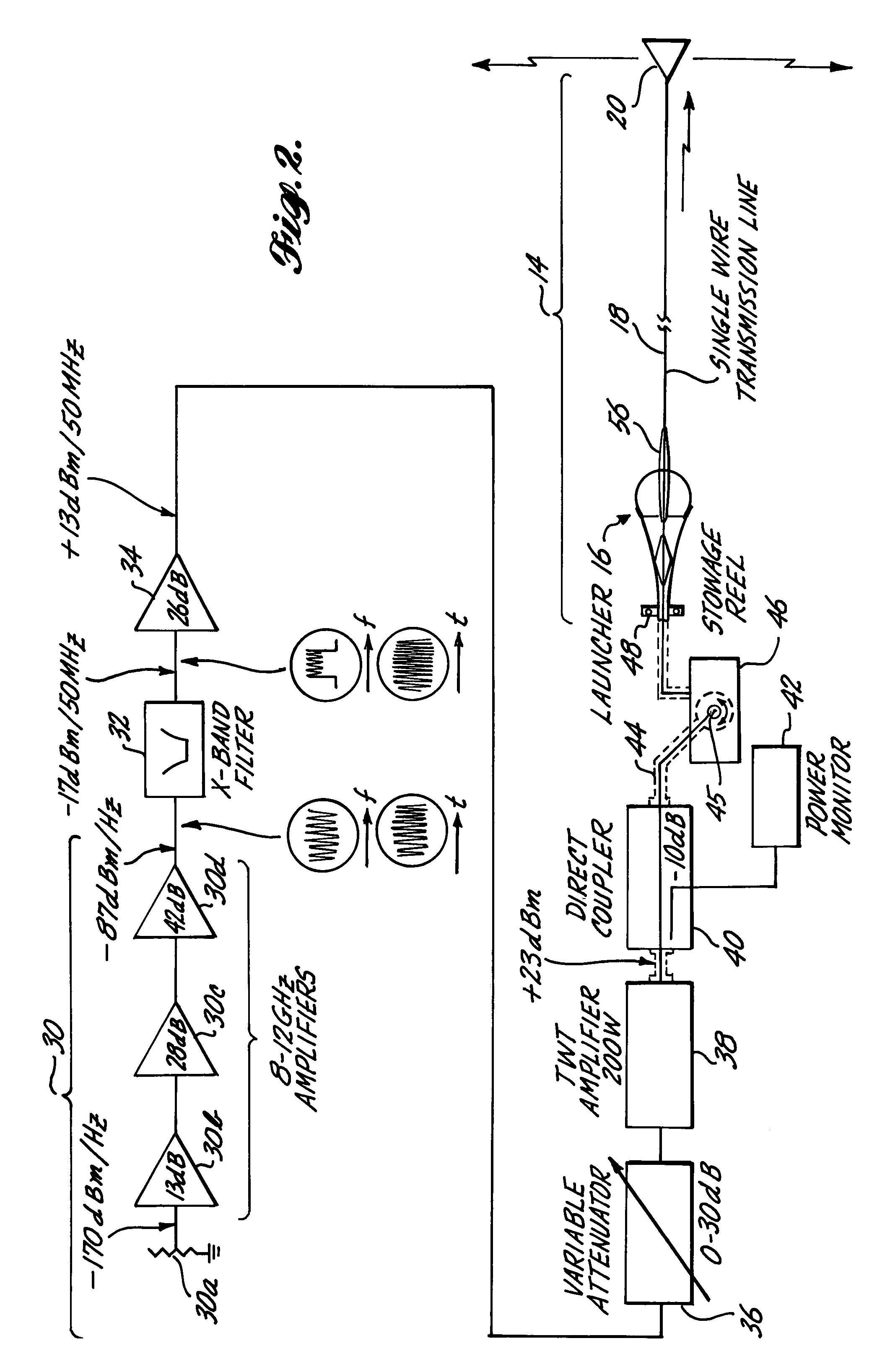
A radar jamming signal generated by equipment carried by a target aircraft, is launched onto the leading end of a towed single wire transmission line so as to travel the length of the line as a nonradiating surface wave. A drogue radiator is attached to the trailing end of the line for radiating the jamming signal transversely of the towed line so as to be received by and cause jamming of tracking and / or fire control radar. The length of the single wire transmission line is selected so that the trailing radiator causes the jamming signal to emanate from a position sufficiently behind the aircraft so as to be outside the destructive radius of weapon fire directed at the apparent source of the jamming signal by fire control radar. A ventriloqual-like deception of the radar is thus achieved. A wave launcher couples the jamming signal to the leading end of the transmission line and for this purpose includes an electrically conducted horn-shaped structure, a tunable coaxial feed end at the constricted end of the horn structure, an inner transition conductor connecting the inner conductor of the coaxial feed to a leading end of the single wire transmission line, and a plurality of annular dielectric lenses and dielectric guides cooperatively shaped and fitted to the horn structure in a manner that effectively matches the bounded electromagnetic transmission wave characteristics of the coaxial feed cable with the surface wave transmission characteristics of the single wire transmission line. Coacting with the ventriloqual-like radiation of the jamming signal from the trailing end of the transmission line is an anti-integration network that hides the return radar signal reflected off the target aircraft in a signal energy “hole” created for such purpose in a secondary low level noise signal transmitted directly from the aircraft.

Description

BACKGROUND OF THE INVENTION[0001]The invention pertains to signal jamming systems, carried by manned or unmanned aircraft including missiles, for the avoidance of position locating, tracking and fire control radar.[0002]The subject matter of the present application is related to a co-pending application, Ser. No. 225,698, filed Jan. 16, 1981 by Walter E. Buehler, David C. Lunden and Michael J. Lewis (BASC-1-0634), entitled Apparatus and Method for Ventriloqual-Like Jamming of Radar Including an Aircraft Towed Single Wire Transmission Line and Wave Launcher Therefor.[0003]The use of radar signal jamming equipment carried onboard manned and unmanned aircraft to mask the aircraft's position from position locating, tracking and fire (weaponry) control radar is one of a number of known radar avoidance techniques that fall in the broader field of electronic counter measures (ECMs). Existing jamming techniques are primarily effective in denying the radar equipment range information, i.e., ...

Claims


Application Information

Patent Timeline
Patent Type & Authority Patents(United States)
IPC IPC(8): G01S7/38G01S7/36H04K3/00
CPCG01S7/38G01S7/36H04K3/46H04K3/42H04K3/43H04K3/68H04K3/825H04K2203/22
Inventor BUEHLER, WALTER E.WHITSON, ROGER M.LEWIS, MICHAEL J.
Owner THE BOEING CO
Learn More