Payload material density calculation and machine using same

a technology of payload material and density calculation, which is applied in the direction of chemical methods analysis, instruments, specific gravity measurement, etc., can solve the problem of undesirable use of additional equipment, including a distance-measuring camera

Active Publication Date: 2014-09-16
CATERPILLAR INC
View PDF28 Cites 25 Cited by
  • Summary
  • Abstract
  • Description
  • Claims
  • Application Information

AI Technical Summary

Problems solved by technology

Although volume information may also be useful in evaluating performance and productivity at a work site, the use of additional equipment, including a distance-measuring camera, may be undesirable.

Method used


Image

  • Payload material density calculation and machine using same
  • Payload material density calculation and machine using same
  • Payload material density calculation and machine using same

Examples


Embodiment Construction

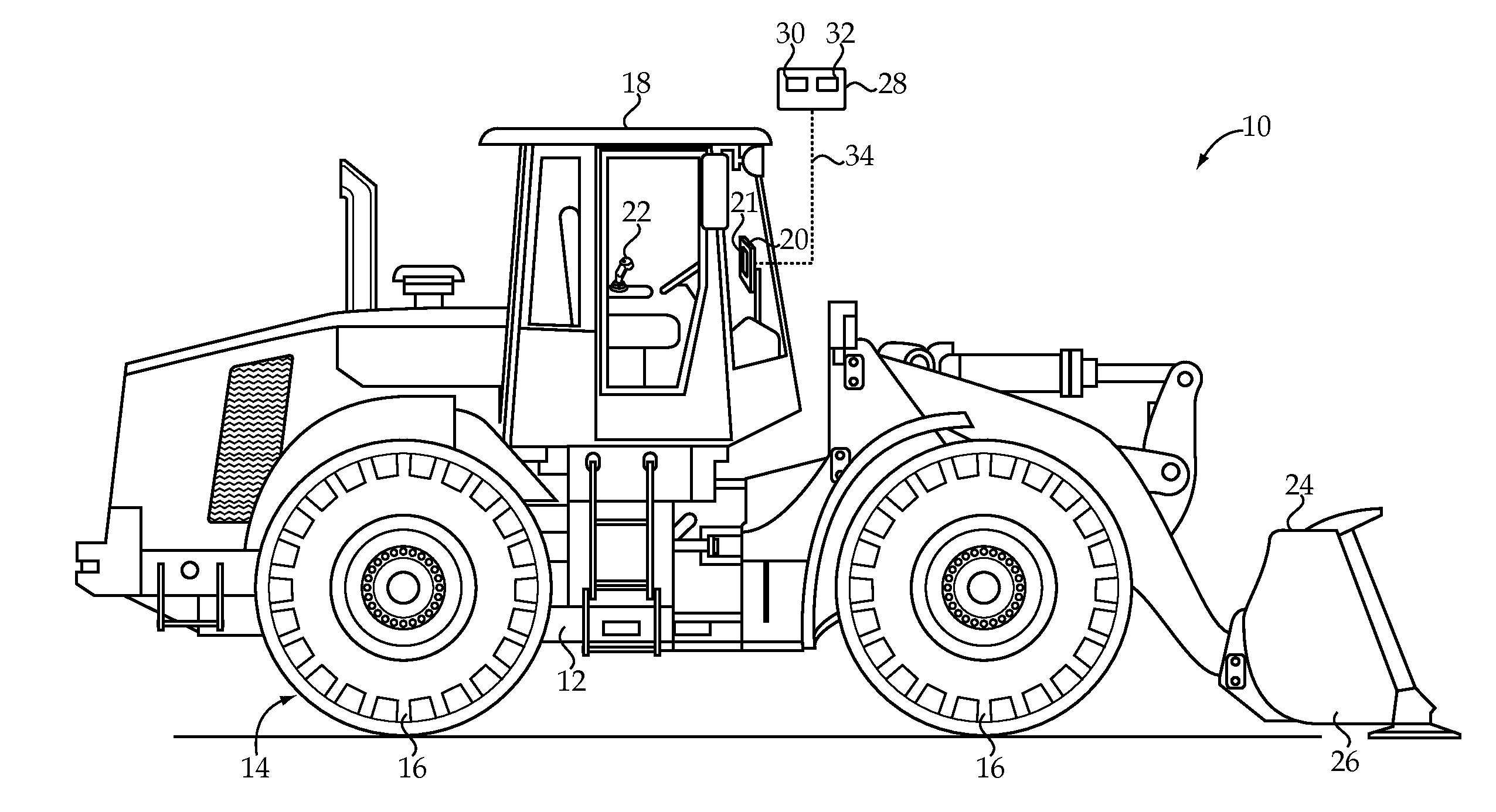
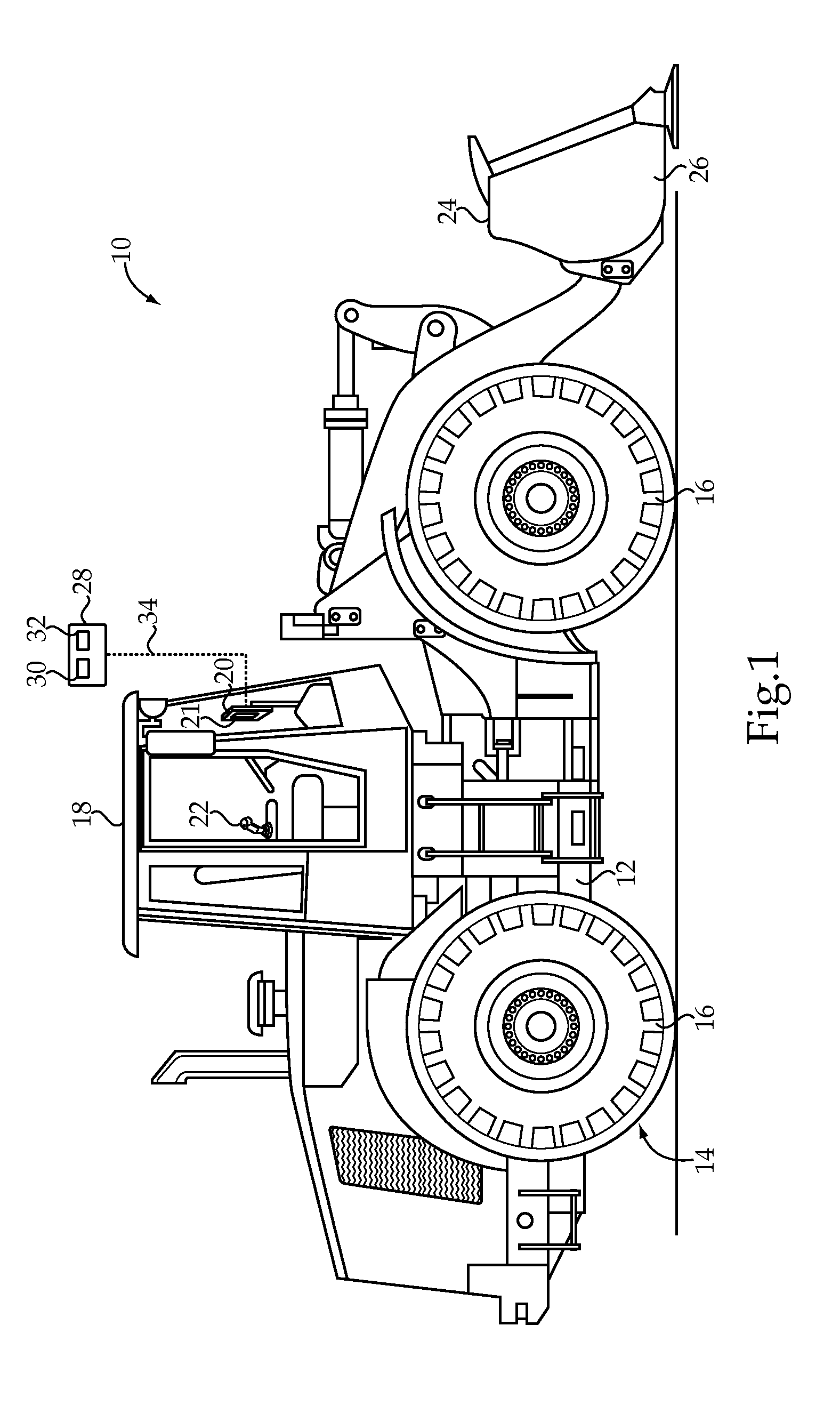
[0015]An exemplary embodiment of a machine 10 is shown generally in FIG. 1. The machine 10 may be an off-highway machine, such as, for example, a wheel loader, or any other machine capable of performing work operations as described herein. The machine 10 generally includes a machine body, or frame, 12 supported by a conveyance 14, which may include wheels 16 (as shown) or alternative ground-engaging propulsion elements. The machine 10 also includes an operator control station 18 supported on the machine body 12 and housing an operator interface 20, including an operator display 21, for displaying various operational information relating to the machine 10 and facilitating operator input of various control information. Additional controls and devices may also be positioned within the operator control station 18, including, for example, one or more controllers 22 for controlling a work tool, or implement, 24, such as a bucket 26 (as shown).

[0016]The machine 10 also includes at least on...


PUM


Abstract

A method of determining payload material density includes a step of determining a capacity volume of a work tool of a machine using an electronic controller of the machine. The work tool is loaded with an initial amount of loaded material matching the capacity volume, and an onboard payload mass calculation algorithm is executed using the electronic controller to determine a mass of the initial amount of loaded material. A density of the initial amount of loaded material is calculated responsive to the mass of the initial amount of loaded material and the capacity volume using the electronic controller. The density of the initial amount of loaded material is stored using the electronic controller, and a productivity datum is calculated responsive to the density of the initial amount of loaded material and a subsequent amount of loaded material.

Description

TECHNICAL FIELD[0001]The present disclosure relates generally to a method of determining density of payload material, and more particularly to determining payload material density based on a capacity volume of a machine work tool and an onboard payload mass calculation of an amount of loaded material matching the capacity volume.BACKGROUND[0002]Off-highway machines, such as, for example, loaders, are typically used to transport a payload material, such as, for example, rock, sand, dirt, or gravel, from one location to another. According to a particular work cycle, the loader may use a work tool, such as a bucket, to capture a portion of the payload material and transfer the captured portion of material to another location. Alternatively, a work cycle may include use of the loader to fill a larger payload capacity machine, such as a haulage truck, which is used to transport the material. According to these work cycles and others, it may be desirable to calculate the weight, or mass, ...

Claims


Application Information

Patent Timeline
Patent Type & Authority Patents(United States)
IPC IPC(8): G01M17/00G06F7/00G06F19/00
CPCG01N9/36E02F3/3411E02F9/2054G06F11/30E02F3/431E02F9/264
Inventor JENSEN, JEFFREY, EDWARD
Owner CATERPILLAR INC
Why Eureka
Try Eureka