Hybrid aircraft having a rotary wing

a hybrid aircraft and wing technology, applied in the direction of rotor aircraft, vertical landing/take-off aircraft, rotorcraft, etc., can solve the problems of affecting the flight speed of the aircraft, and possesses a relatively complex power transmission system to the main rotor, so as to minimize the loss of lift that results from the wing during the hovering flight, and optimize the power efficiency of the anti-torque function

Active Publication Date: 2014-09-23
EUROCOPTER
View PDF38 Cites 16 Cited by
  • Summary
  • Abstract
  • Description
  • Claims
  • Application Information

AI Technical Summary

Benefits of technology

[0042]The invention thus makes it possible to present one or more of the following advantages compared with a conventional helicopter:
[0094]Under such circumstances, the loss of lift that results from the wing during hovering flight is minimized.

Problems solved by technology

Of those various rotorcraft formulae, the helicopter is the simplest, such that it is the most widespread in spite of the fact that the maximum forward speed of a helicopter is about 300 kilometers per hour (km / h) which is slow and less than the speed that can be envisaged with formulae of the compound or convertible types, that are technically more complex and more expensive.
That rotorcraft thus possesses a system for transmitting power to the main rotors that is relatively complex.
In addition, the propeller is potentially situated in the wake of the fuselage and of a main rotor, which can give rise to noise and to the phenomenon known as “tail shake”.
It should be observed in particular that it is not possible in hovering flight to stop the propeller from rotating, that propeller then requiring power, even when providing no thrust.

Method used


Image

  • Hybrid aircraft having a rotary wing
  • Hybrid aircraft having a rotary wing

Examples


Embodiment Construction

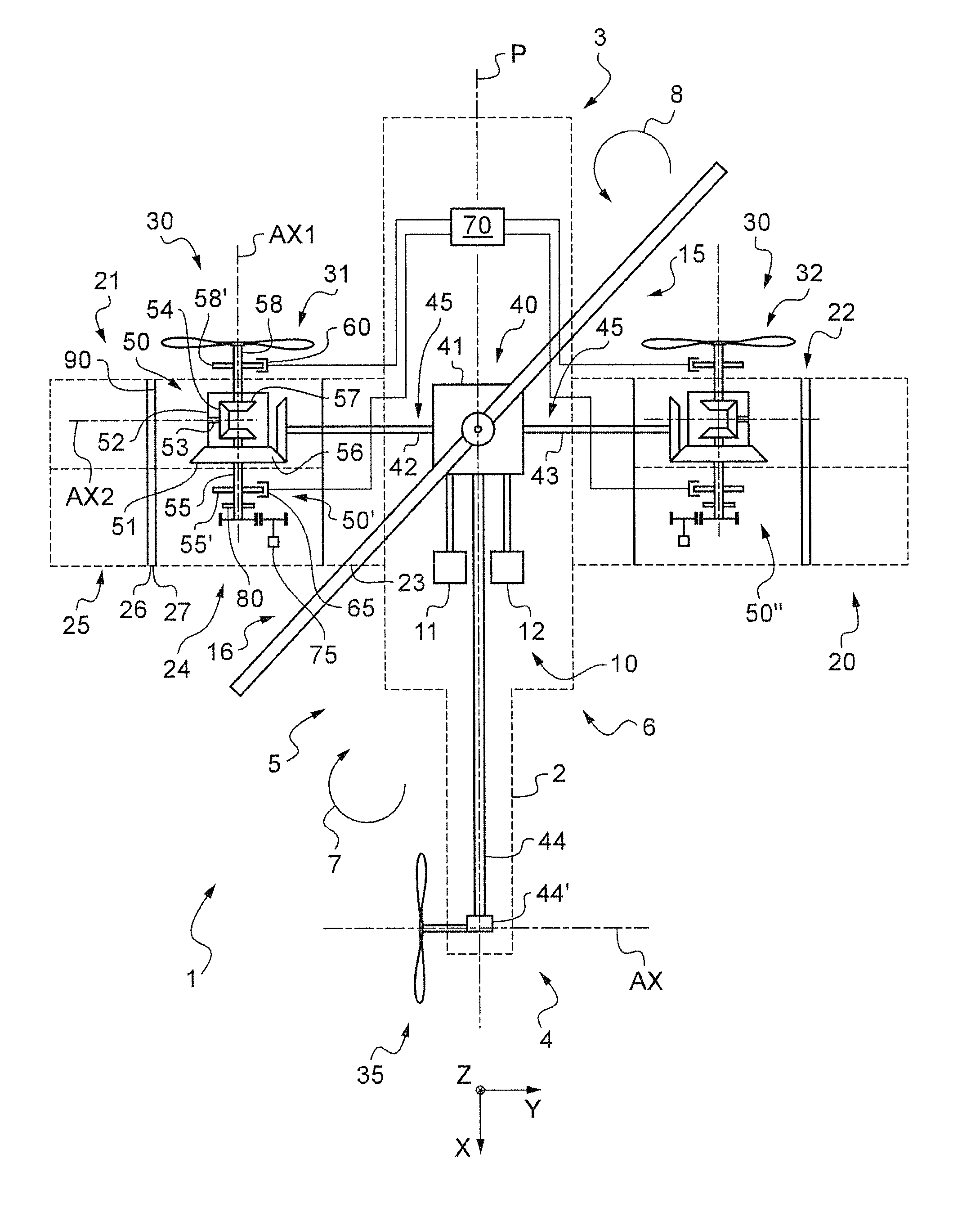
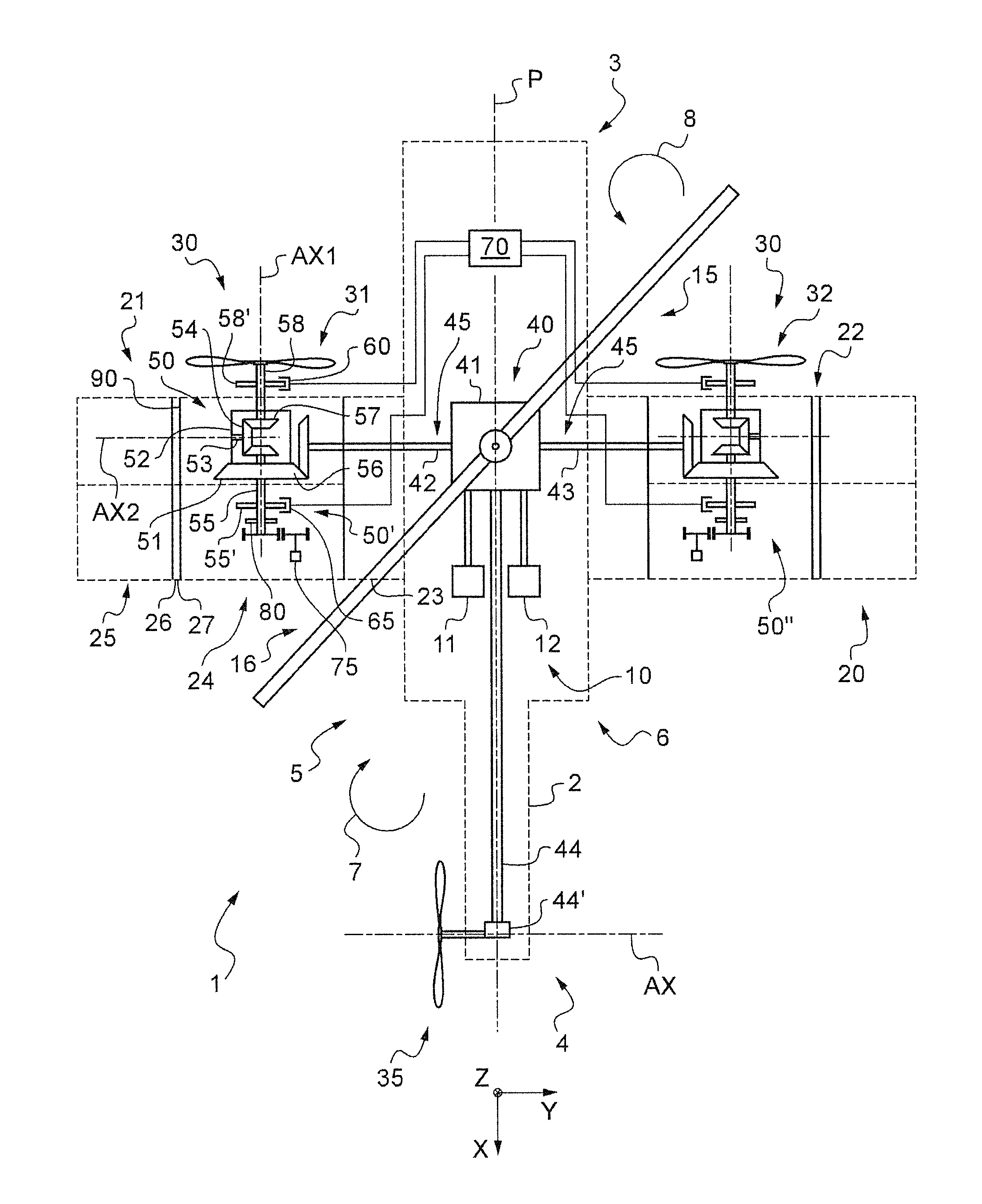
[0102]The FIGURE shows an aircraft 1 having a fuselage 2.

[0103]The fuselage 2 extends longitudinally from a nose 3 to a rear end 4 along an anteroposterior plane of symmetry P, transversely from a first side 5 to a second side 6, and in elevation from a bottom portion 7 to a top portion 8.

[0104]The aircraft also includes a rotary wing 15 above the top portion 8 of the fuselage, the rotary wing comprising at least one main rotor 16.

[0105]The aircraft is also provided with a tail rotor 35 arranged at the rear end 4. The tail rotor 35 rotates about a transverse axis AX in particular in order to counter the torque exerted by the main rotor 16 on the fuselage 2 and in order to control the aircraft in yaw.

[0106]Furthermore, the aircraft 1 has a fixed wing 20, this wing comprising two half-wings 21 and 22 extending on either side of the fuselage, e.g. in a transverse direction.

[0107]Each half-wing 21, 22 carries a propulsive propeller 30, the first half-wing 21 carrying a first propeller 3...


PUM


Abstract

An aircraft (1) having a fuselage (2), a power plant (10), a rotary wing (15) having at least one main rotor (16), and a fixed wing (20) comprising two half-wings (21, 22) extending on either side of the fuselage (2). The aircraft (1) also has at least two propulsive propellers (30) on either side of the fuselage (2). Each is positioned on respective ones of the half-wings (21, 22), and an anti-torque and yaw-control tail rotor (35). A transmission system (40) connects the power plant (10) to each main rotor (16) and the tail rotor (35). The transmission system (40) connects the power plant (10) to each propeller (30) via a respective differential mechanism (50) that is controllable on request so that each propeller (30) can be driven in cruising flight and need not be driven in rotation by the power plant (10) on the ground or while hovering.

Description

CROSS REFERENCE TO RELATED APPLICATIONS[0001]This application claims priority to French Patent Application No. FR 11 02947 filed on Sep. 29, 2011, the disclosure of which is incorporated in its entirety by reference herein.BACKGROUND OF THE INVENTION[0002](1) Field of the Invention[0003]The present invention relates to a hybrid aircraft having a rotary wing and suitable for traveling long distances at high speed.[0004]This advanced rotorcraft design seeks, at reasonable cost, to combine the effectiveness in vertical flight of a conventional helicopter with the high travel speed performance made possible by using propulsive propellers and modern engines.[0005](2) Description of Related Art[0006]In order to understand clearly the object of the invention, it is appropriate to recall the main kinds of flying machine that correspond to aircraft and to rotorcraft.[0007]The term “rotorcraft” designates any aircraft in which lift is provided in full or in part by at least one rotary wing. T...

Claims


Application Information

Patent Timeline
Patent Type & Authority Patents(United States)
IPC IPC(8): B64C27/22B64D35/04B64C27/26B64C27/12B64C27/82
CPCB64C27/26B64C27/82B64C27/12B64C27/22B64C29/00B64D35/04
Inventor MORET, ROBIN
Owner EUROCOPTER
Why Eureka
Try Eureka