Apparatus for infection control

a technology of apparatus and fluid, applied in the field of sterilization of flowing fluid, can solve problems such as ineffectiveness, and achieve the effect of reducing device size and efficient destruction of microorganisms

Inactive Publication Date: 2014-09-23
INCEPTUS TECH
View PDF19 Cites 2 Cited by
  • Summary
  • Abstract
  • Description
  • Claims
  • Application Information

AI Technical Summary

Benefits of technology

[0006]Accordingly, an object of the invention is a device for sterilizing fluid flows. For a device of this type, the use of turbulence and reflectivity with an appropriate light source may allow for efficient microorganism destruction of material passing through a lumen and reduce device size, allowing for a variety of applications. The use of a flexible or folding device may allow for the navigation of tortuous paths for delivery and use of the device in areas that would otherwise not be feasible.
[0012]Another embodiment of the invention is an apparatus for in vivo sterilization of a respirator circuit. The device may be composed of a tubular structure which is composed of an inlet and outlet that reduces the emission of UV light out of the invention, referred to as a light trap, but allows fluid to flow through the invention. A light trap may be composed of any structure that reduces or prevents light from passing, escaping, or being transmitted. The device may be placed into the respirator tubing between the respirator machine and the patient. It may be placed in the balloon portion of the tracheal tube, at the end of the tracheal tube, or further within the tracheal tube so as to sterilize the airflow, aspirated material, and secretions. External o-rings may be present to assure that fluid flow passes through the lumen of the device. The volume between the inlet and outlet may contain ultraviolet light sources reflective surfaces, and turbulence inducing features, which cause the fluid to be exposed to the light from more directions and for longer times than would be possible otherwise. The light sources may be powered by electrical induction from a magnetic coil external to the device and respirator tubing or by other appropriate power sources.

Problems solved by technology

This is not completely effective however in that not all TB patients will be wearing a mask.

Method used


Image

  • Apparatus for infection control
  • Apparatus for infection control
  • Apparatus for infection control

Examples


Embodiment Construction

[0033]Reference will now be made to various embodiments of the apparatus for infection control, examples of which are illustrated in the accompanying drawings, wherein like numerals indicate the same element throughout views.

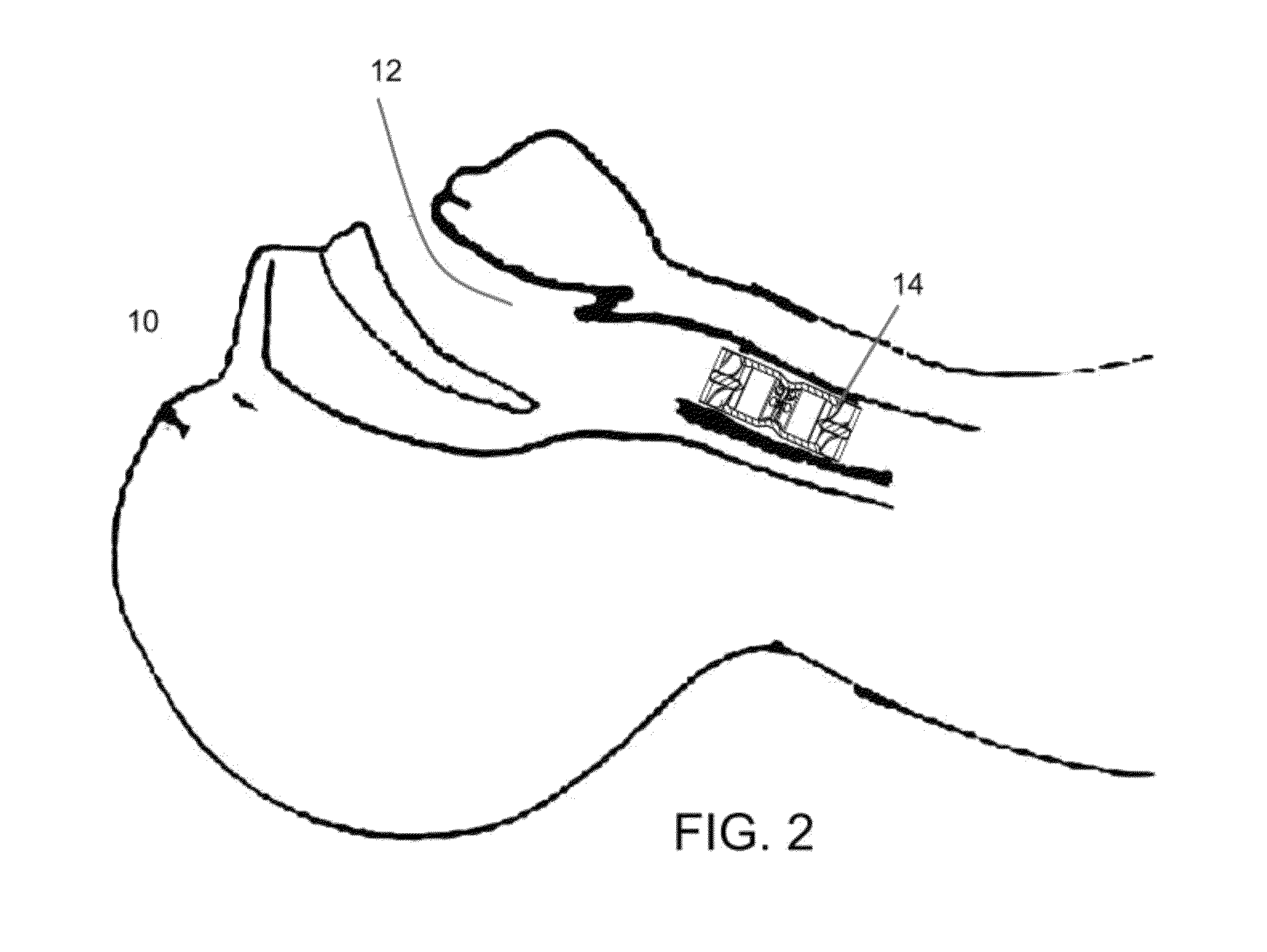
[0034]FIG. 2 depicts an embodiment of the apparatus for infection control. In this embodiment, an apparatus for infection control 14 is shown in a patient's trachea 12. The patient 10 is shown positioned for implantation. The device could also be located less or more deep in the tracheal path, including in the bronchi. The device could also be implanted into the nasal cavity to sterilize nasal air while allowing higher air flows through the mouth when needed. In this embodiment, the apparatus for infection control can sterilize both air inhaled by the patient and the air exhaled by the patient. Sterilization of exhalation may support the containment of contagious disease or other biological contaminants.

[0035]FIG. 3 depicts an apparatus for infection control 18 ...


PUM

PropertyMeasurementUnit
wavelengthaaaaaaaaaa
frequencyaaaaaaaaaa
poweraaaaaaaaaa

Abstract

A device that can sterilize material passing through it efficiently by utilizing an appropriate light source that can be powered by external sources (including use of an electromagnetic field to transmit energy) or by a power source that is contained within the device itself, which may include elements to create turbulence within the material passing through it, and elements to reflect the light source where useful but trap the light from escaping to ensure safety. The device may be rigid or flexible, possibly including a mechanism to fold or collapse the device for delivery through a port or lumen and expanded or unfolded prior to use.

Description

FIELD OF THE INVENTION[0001]Field of the invention relates to sterilization of a flowing fluid by method of novel placement of one or more light sources relative to the fluid and / or novel powering of light sources and / or use of turbulence and / or reflective surfaces to allow for use in a variety of environments, geometries, and applications.BACKGROUND OF THE INVENTION[0002]The need for infection control exists in many different situations and can be used to address many different needs. One of the apparent applications for infection control is in medicine. From device sterilization to drugs to address infection to topical application of infection fighting compounds to air handling to simple handwashing, much of medicine is focused on the need to provide infection control.[0003]The need is particularly acute, for example in dealing with tuberculosis (TB), which as cited in U.S. Pat. No. 6,497,840 (8 Nov. 1993) by Palestro, et al, is the most common cause of infectious disease in the w...

Claims


Application Information

Patent Timeline
Patent Type & Authority Patents(United States)
IPC IPC(8): A61N5/06A61L9/20A61M16/04
CPCA61M16/1065A61M16/04A61L9/20A61M16/107A61M2205/053A61M16/1055
Inventor ABBOTT, RYANGINNEBAUGH, FREDERICK ALEXANDER
Owner INCEPTUS TECH
Why Eureka
Try Eureka