Position detection apparatus, imprint apparatus, and position detection method

a technology of position detection and imprint, which is applied in the direction of photomechanical equipment, instruments, manufacturing tools, etc., can solve the problem of difficulty in detecting the alignment mark, and achieve the effect of easy detection

Active Publication Date: 2014-09-23
CANON KK
View PDF5 Cites 17 Cited by
  • Summary
  • Abstract
  • Description
  • Claims
  • Application Information

AI Technical Summary

Benefits of technology

[0008]The present invention is directed to allowing a mark to be easily detected by making an amount of diffracted light from the mark used in an alignment large.

Problems solved by technology

Accordingly, an amount of diffracted light from the diffraction grating is small, and it is difficult to detect a mark used for alignment.

Method used


Image

  • Position detection apparatus, imprint apparatus, and position detection method
  • Position detection apparatus, imprint apparatus, and position detection method
  • Position detection apparatus, imprint apparatus, and position detection method

Examples


Embodiment Construction

[0026]Various exemplary embodiments, features, and aspects of the invention will be described in detail below with reference to the drawings.

[0027]An imprint apparatus according to the first exemplary embodiment will be described with reference to FIG. 1.

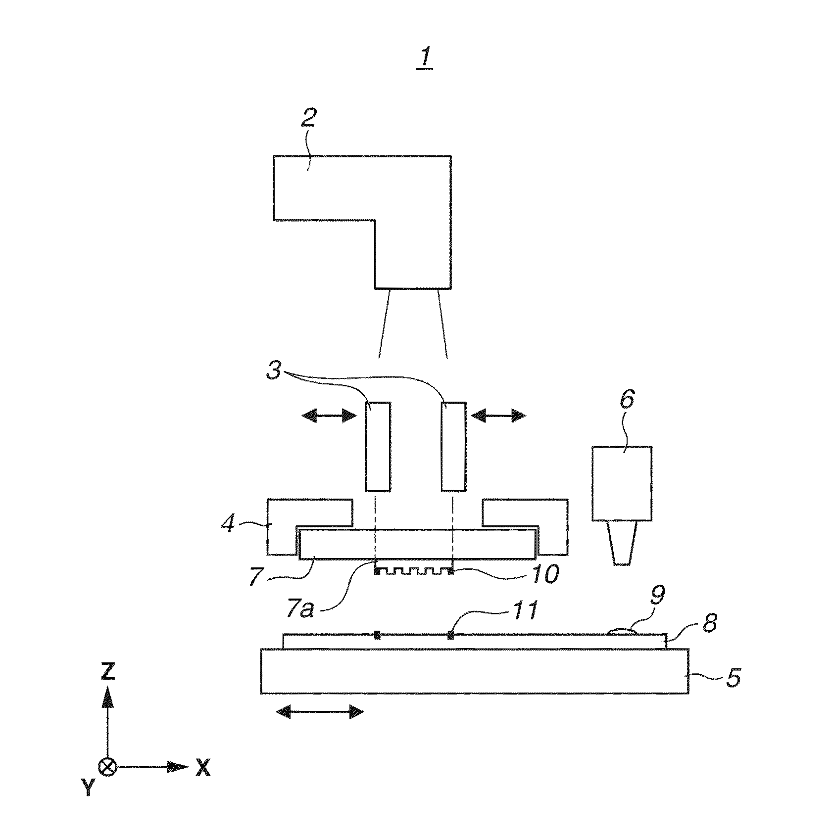
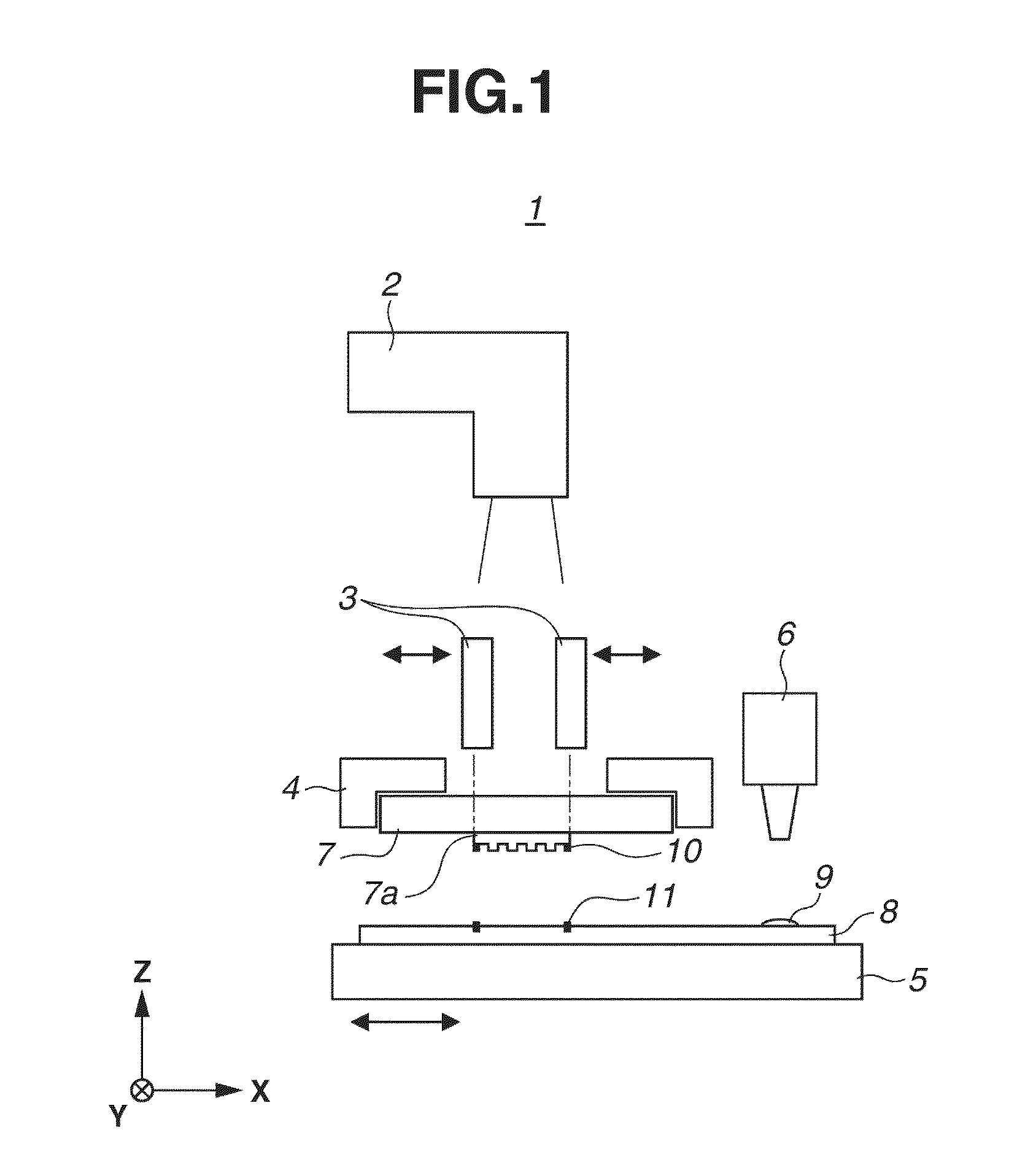
[0028]FIG. 1 is a schematic view illustrating a configuration of an imprint apparatus according to the first exemplary embodiment. The imprint apparatus is an apparatus for molding an imprint material (resin) supplied to a substrate which is an object to be processed with a mold to transfer a pattern onto the substrate. For example, the imprint apparatus is used to manufacture a device such as a semiconductor device. In the following drawings, the X-axis and Y-axis orthogonal to each other are set on a plane parallel to the substrate and the mold, and the Z-axis is set in a direction orthogonal to the X-axis and the Y-axis.

[0029]The imprint apparatus 1 includes a irradiation unit 2, a detection unit 3, a mold holding unit 4, a subst...


PUM

PropertyMeasurementUnit
degrees of freedomaaaaaaaaaa
sizeaaaaaaaaaa

Abstract

A position detection apparatus includes an illumination optical system for illuminating a first diffraction grating having periods in each of a first direction and a second direction different from the first direction, and a second diffraction grating having a period different from the period in the second direction of the first diffraction grating in the second direction, at an oblique incidence, and a detection optical system for detecting diffracted light from the first diffraction grating and the second diffraction grating, wherein a relative position of the first diffraction grating and the second diffraction grating is detected based on the detected diffracted light, and wherein the illumination optical system includes a plurality of light intensity distributions in the first direction except for on an optical axis of the detection optical system, in a pupil plane thereof.

Description

BACKGROUND OF THE INVENTION[0001]1. Field of the Invention[0002]The present invention relates to a position detection apparatus which detects a relative position between two different objects, an imprint apparatus, and a position detection method.[0003]2. Description of the Related Art[0004]Imprint technology is technology for forming a fine pattern on a substrate by using a mold having a pattern. For example, such an imprint technology includes photo-curing method. In the imprint technology using photo-curing method, first, a resin (imprint resin, photo curable resin) which serves as an imprint material is supplied to a shot which serves as an imprint region on a substrate (wafer). The resin is cured by bringing the resin into contact with a pattern of the mold (imprinting) and radiating light while the resin and the pattern are in contact with each other. The resin pattern is formed on the substrate by separating the mold from the cured resin.[0005]When the resin on the substrate ...

Claims


Application Information

Patent Timeline
Patent Type & Authority Patents(United States)
IPC IPC(8): G01B11/14G01D5/38G03F7/00G03F9/00
CPCG03F7/0002G03F9/7076G03F9/7038G03F9/7049G01D5/38G03F9/7069G02B5/18B82Y40/00B29D11/00769B82Y10/00B29L2011/00Y10T29/49769B29C59/026G01B11/14G01D5/34723H01L21/0273
Inventor MINODA, KENSHIODE, YOSHIHIROMISHIMA, KAZUHIKOMAEDA, HIRONORI
Owner CANON KK
Why Eureka
Try Eureka