Spectrophotometer having prompt spectrophotometric measurement
a spectrophotometer and prompt technology, applied in the field of spectrophotometers, can solve the problems of reducing the time interval during which measurement is performed, increasing the time required for measurement, and difficulty in obtaining a light intensity at a so as to achieve more prompt spectrophotometric measurement, accurate voltage to be measured, and simplify processing
- Summary
- Abstract
- Description
- Claims
- Application Information
AI Technical Summary
Benefits of technology
Problems solved by technology
Method used
Image
Examples
first embodiment
[0040]Hereinafter, a first embodiment according to the invention will be described based on the drawings.
Configuration of a Spectrophotometer
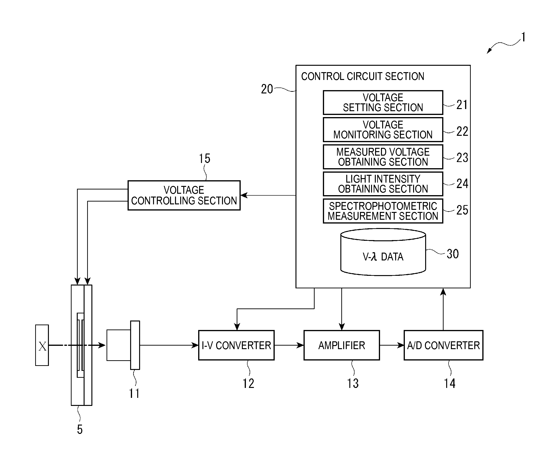
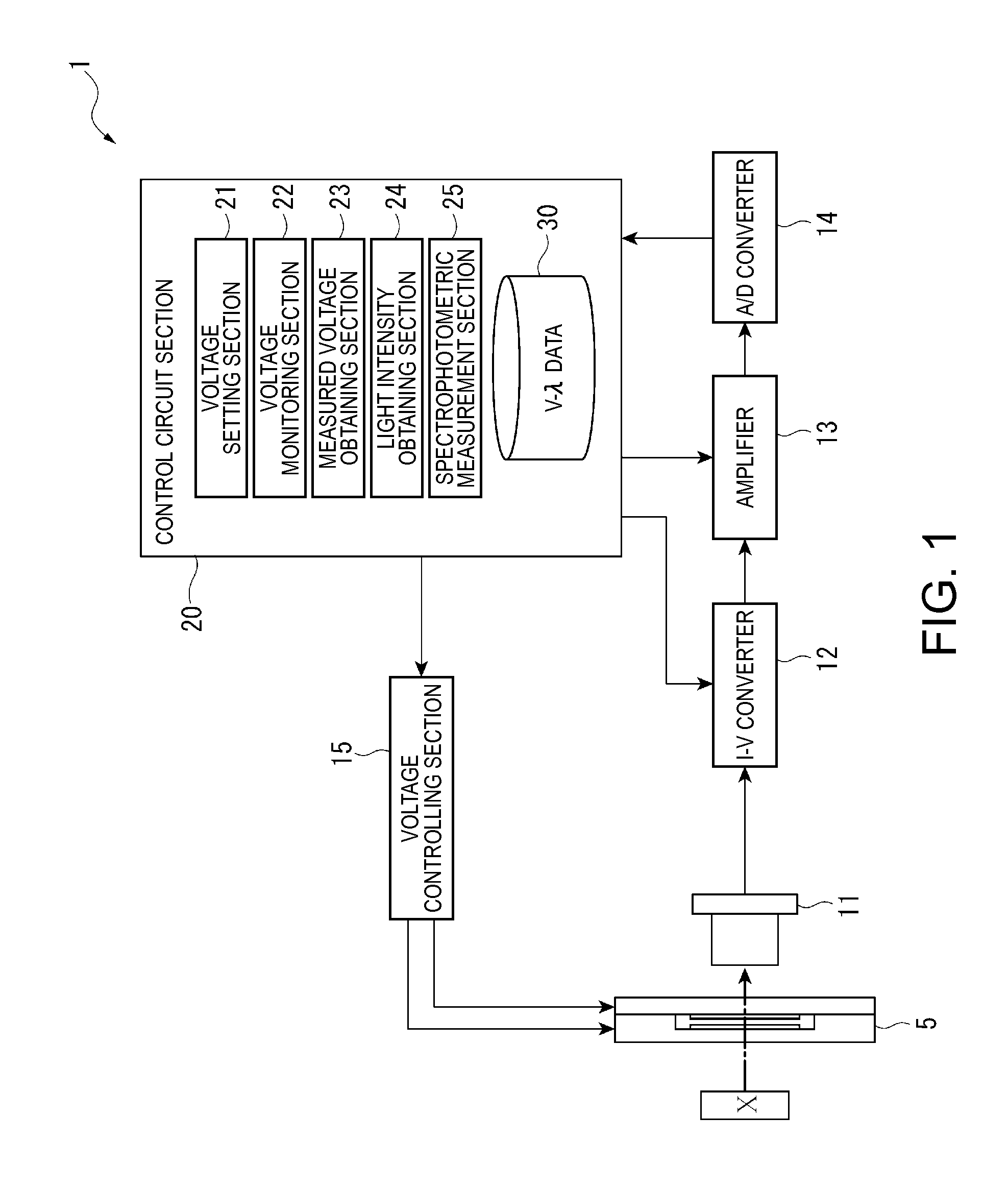
[0041]FIG. 1 is a block diagram showing a schematic configuration of a spectrophotometer according to the embodiment of the invention.
[0042]A spectrophotometer 1 is an apparatus that measures the spectrum of a light to be measured by analyzing the light intensity of the light to be measured at each wavelength, the light reflected from an object X to be measured, for example. Incidentally, in this embodiment, an example in which a light to be measured, reflected from the object X to be measured, is measured is described. When a light emitter such as a liquid crystal panel is used as the object X to be measured, the light emitted from the light emitter may be used as the light to be measured.
[0043]As shown in FIG. 1, the spectrophotometer 1 includes a tunable interference filter 5, a detecting section 11, an I-V converter 12, an amplifier 13, an ...
second embodiment
[0103]Next, a second embodiment according to the invention will be described based on the drawing.
[0104]In the spectrophotometer of the first embodiment described above, as shown in FIGS. 4 and 5, the light intensity obtaining section 24 obtains a light intensity once at each set voltage to be measured. On the other hand, a spectrophotometer of the second embodiment differs from the spectrophotometer of the first embodiment described above in that a plurality of light intensities are obtained at each voltage to be measured. Incidentally, since the component elements forming the spectrophotometer of the second embodiment are the same as those of the first embodiment described above, their descriptions will be omitted.
[0105]FIG. 7 is a diagram showing the relationship between the time and the inter-reflecting coating gap G1 when a periodical drive voltage is applied to the tunable interference filter 5 in the second embodiment.
[0106]As shown in FIG. 7, the light intensity obtaining se...
third embodiment
[0109]Next, a third embodiment according to the invention will be described based on the drawing.
[0110]In the first and second embodiments described above, the measured voltage obtaining section 23 obtains a voltage to be measured based on the V-λ data stored in the storing section 30. On the other hand, a spectrophotometer of this embodiment differs from the spectrophotometers of the first and second embodiments described above in that a gap distance detecting section detecting the gap distance of the inter-reflecting coating gap G1 is provided in the tunable interference filter and a voltage to be measured is obtained based on the gap distance detecting section.
[0111]FIG. 8 is a block diagram showing a schematic configuration of the spectrophotometer of the third embodiment. Moreover, FIG. 9 is a plan view showing a schematic configuration of a tunable interference filter of the third embodiment, and FIG. 10 is a sectional view of the tunable interference filter. In a tunable inte...
PUM
 Abstract
Description
Claims
Application Information
 - R&D
- Intellectual Property
- Life Sciences
- Materials
- Tech Scout
- Unparalleled Data Quality
- Higher Quality Content
- 60% Fewer Hallucinations
Browse by: Latest US Patents, China's latest patents, Technical Efficacy Thesaurus, Application Domain, Technology Topic, Popular Technical Reports.
© 2025 PatSnap. All rights reserved.Legal|Privacy policy|Modern Slavery Act Transparency Statement|Sitemap|About US| Contact US: help@patsnap.com


