In-situ battery diagnosis method using electrochemical impedance spectroscopy

a technology of impedance spectroscopy and in-situ battery, which is applied in the direction of material analysis, speed/acceleration/shock measurement, instruments, etc., can solve the problems of overestimation of the number, difficult to drive, and gradual degradation of the performance of the battery

Inactive Publication Date: 2014-09-30
INST FR DU PETROLE
View PDF19 Cites 14 Cited by
  • Summary
  • Abstract
  • Description
  • Claims
  • Application Information

AI Technical Summary

Benefits of technology

[0031]The differing internal states can be obtained through accelerated aging of a second electrochemical system for electrical power storage of the same type as the first electrochemical system. These differing internal states can also be obtained by selecting a set of second electrochemical systems of the same type as the first electrochemical system with the systems of the set having different internal states.

Problems solved by technology

During the life of a battery, its performances tend to degrade gradually because of the physical and chemical variations that occur while it is being used, until it becomes unusable.
A wrong diagnosis of the state of charge can lead to an overestimation of the number of kilometers that can be traveled and put the motorist in a difficult position.
These methods however lead to estimation of errors by disregarding phenomena such as self-discharge.
However, these dependencies are in reality much more complicated than what is normally taken into account in the BMS, which often leads to SoC estimation errors.
This method however requires much instrumentation, notably for inserting a reference electrode in the element, and more complex electronic management of the battery.
However, this method is more difficult to implement for Li-ion type elements whose response variations after this type of perturbation are very low and can therefore not allow precise SoH measurement.

Method used


Image

  • In-situ battery diagnosis method using electrochemical impedance spectroscopy
  • In-situ battery diagnosis method using electrochemical impedance spectroscopy
  • In-situ battery diagnosis method using electrochemical impedance spectroscopy

Examples


example 1

Case of an Element of Chemical Composition LFP / C

[0112]Stage 1

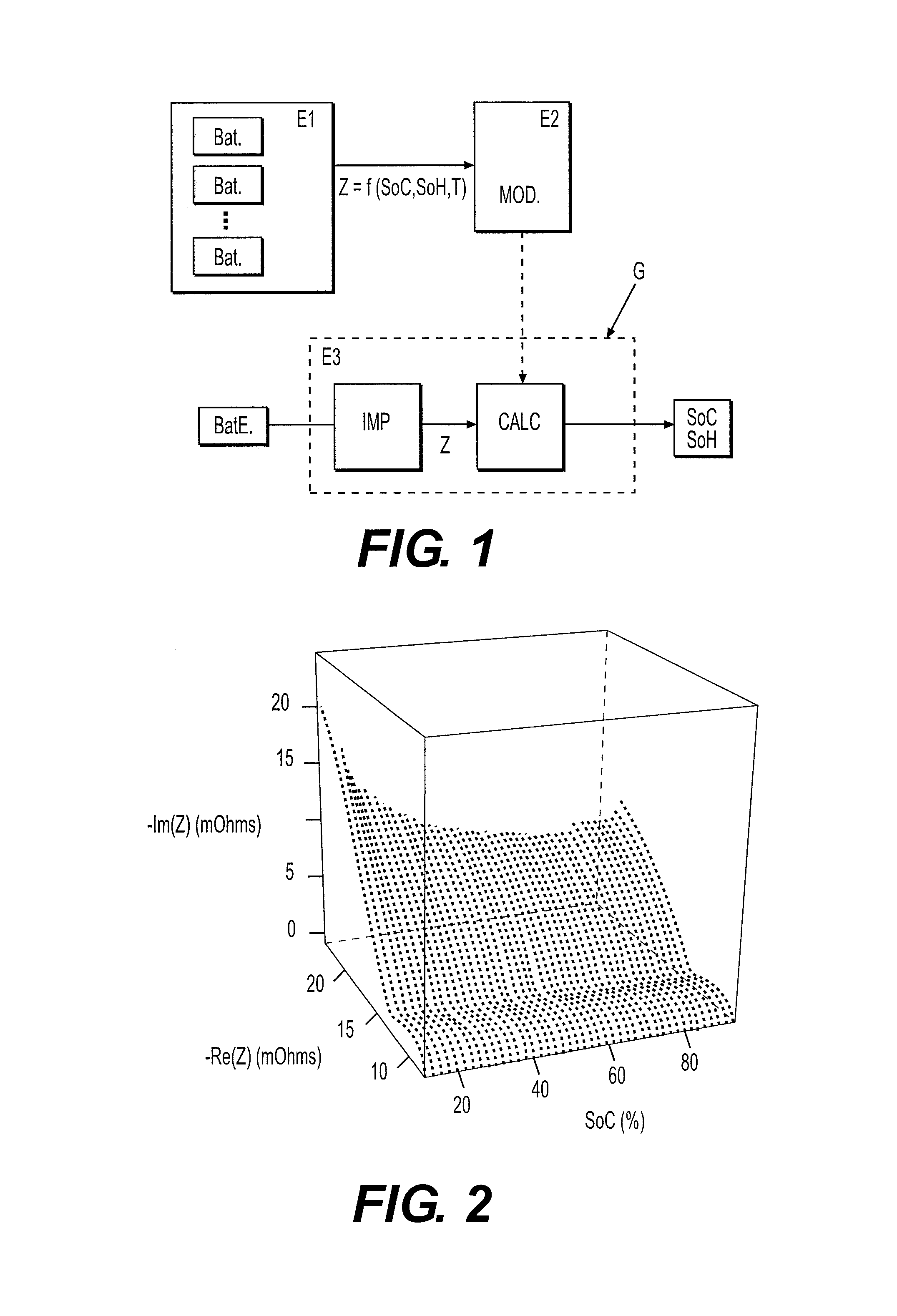
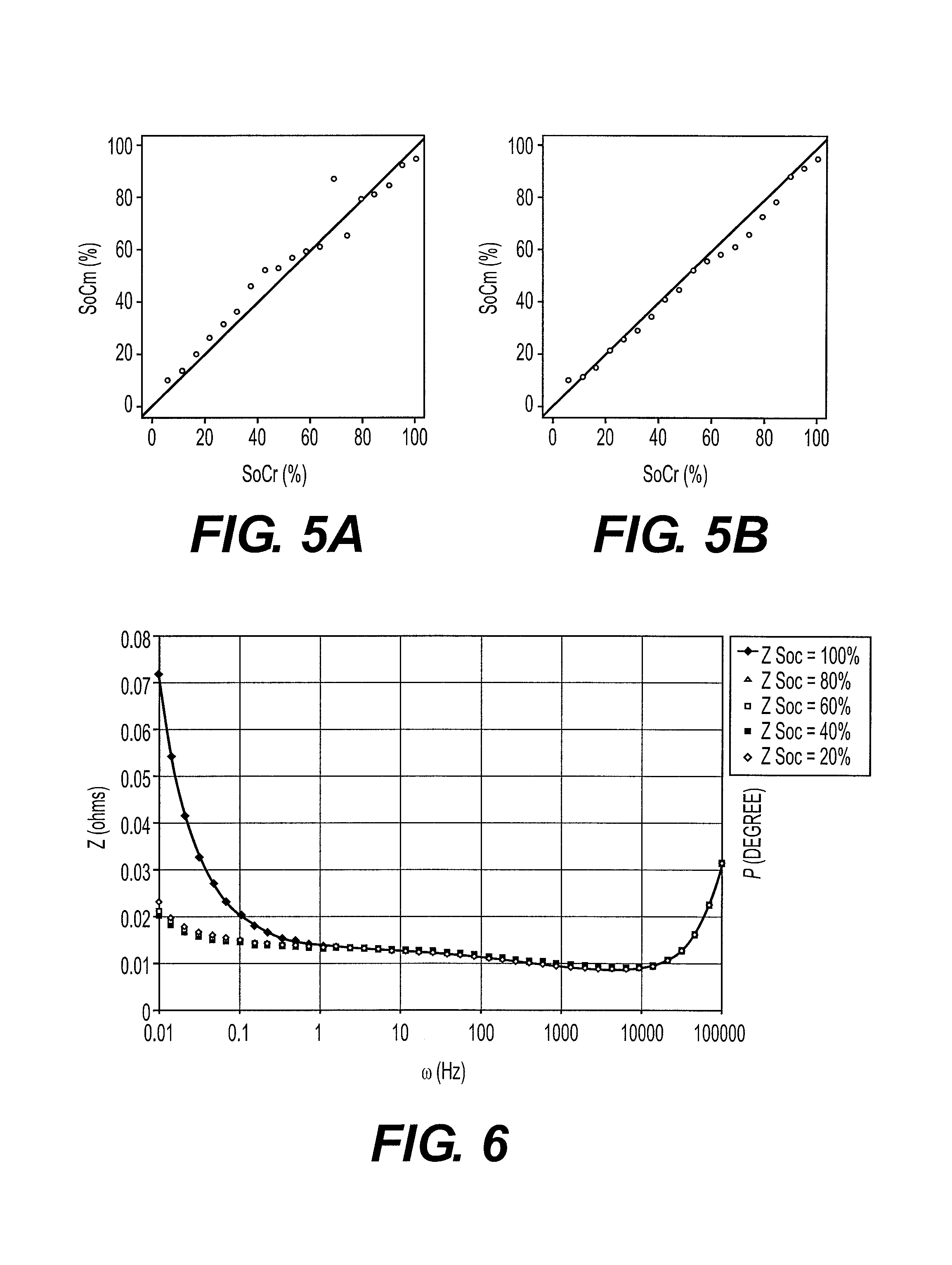
[0113]FIG. 6 illustrates a Bode diagram wherein ω represents the frequency in Hz, P represents the phase in degrees and Z represents the electrochemical impedance modulus in Ohms. This diagram allows comparison of the impedances determined for states of charge on a C / LFP type battery. These impedances were obtained using successively sinusoidal signals of different frequencies. The impedances can also be obtained differently, for example by superposing a white noise on the battery charge / discharge signals.

[0114]It should be noted that, in the diagram, the impedances are not superimposed and that they evolve as a function of the charged capacity.

[0115]Stage 2

[0116]These differences are quantified according to the invention by adjusting an impedance model on the curves of the impedance diagram by means of the formula as follows:

[0117]Z⁡(ω,SoC)=a*ⅈ*ω+b+1c1+d1*ⅈ*ωn1+1c2+d2*ⅈ*ωn2

where a, b, c1, d1, n1, c2, d2 and n2 are paramet...

example 2

Case of an Element of Chemical Composition NCO / C

[0124]This new example allows testing the robustness of the method according to the invention for various battery technologies. The impedance diagram (Nyquist diagram) with 50% SoC of the NCO / C technology is shown in FIG. 9. The shape of this curve suggests the convolution of 3 semi-circles, which allows defining the model as follows:

[0125]Z⁡(ω,SoC)=a*ⅈ*ω+b+1c1+d1*ⅈ*ωn1+1c2+d2*ⅈ*ωn2+1c3+d3*ⅈ*ωn3

where a, b, c1, d1, n1, c2, d2, n2, c3, d3 and n3 are parameters to be adjusted according to the experimental values.

[0126]By proceeding as in the previous example, this model is adjusted on the impedance diagrams as a function of the frequency, the state of charge and the temperature, and leads to an impedance model as a function of the SoC, the temperature and the frequency.

[0127]Using another element of identical chemical composition, of known SoC, and the previous model, it is possible to calculate the SoC of this element from a determinatio...


PUM


Abstract

A method of estimating the internal state of a first electrochemical system for power storage is disclosed. The SoC and the electrochemical impedance are determined for different internal states of a second electrochemical system of a same type as the first electrochemical system being studied. An electrochemical impedance model is then defined as a function of the SoC and of parameters. The electrochemical impedance Z of the system studied is determined and its SoC is estimated using the model applied to electrochemical impedance Z.

Description

CROSS REFERENCE TO RELATED APPLICATION[0001]Reference is made to French application Ser. No. 10 / 03.820, filed Sep. 27, 2010, which application is incorporated herein by reference in its entirety.BACKGROUND OF THE INVENTION[0002]1. Field of the Invention[0003]The present invention relates to a method of estimating the internal state of an electrochemical system for electrical power storage, such as a battery (lead, Ni-MH, Li-ion, etc.). The method allows management of batteries used in stationary or on-board applications, notably during the operation thereof.[0004]2. Description of the Prior Art[0005]The battery is one of the most critical components in the case of hybrid or electrical vehicle applications. Proper operation of these applications is based on a smart battery management system (BMS) whose purpose is to operate the battery with the best compromise between the various dynamic demand levels. The BMS requires precise and reliable knowledge of the state of charge (SoC) and o...

Claims


Application Information

Patent Timeline
Patent Type & Authority Patents(United States)
IPC IPC(8): G06F19/00G01R31/36
CPCG01R31/3662G01R31/3651G01R31/389G01R31/367
Inventor MINGANT, REMYBERNARD, JULIENSAUVANT-MOYNOT, VALERIE
Owner INST FR DU PETROLE
Why Eureka
Try Eureka