
Ignition coil of engine

a technology of ignition coil and engine, which is applied in the direction of ignition safety means, machines/engines, spark plugs, etc., can solve the problems of difficult achieve the effects of effective removal of noise, dissipation of heat, and prevention of inflow

Active Publication Date: 2014-10-07
HYUNDAI MOTOR CO LTD +1
View PDF16 Cites 0 Cited by
  • Summary
  • Abstract
  • Description
  • Claims
  • Application Information

AI Technical Summary

Benefits of technology

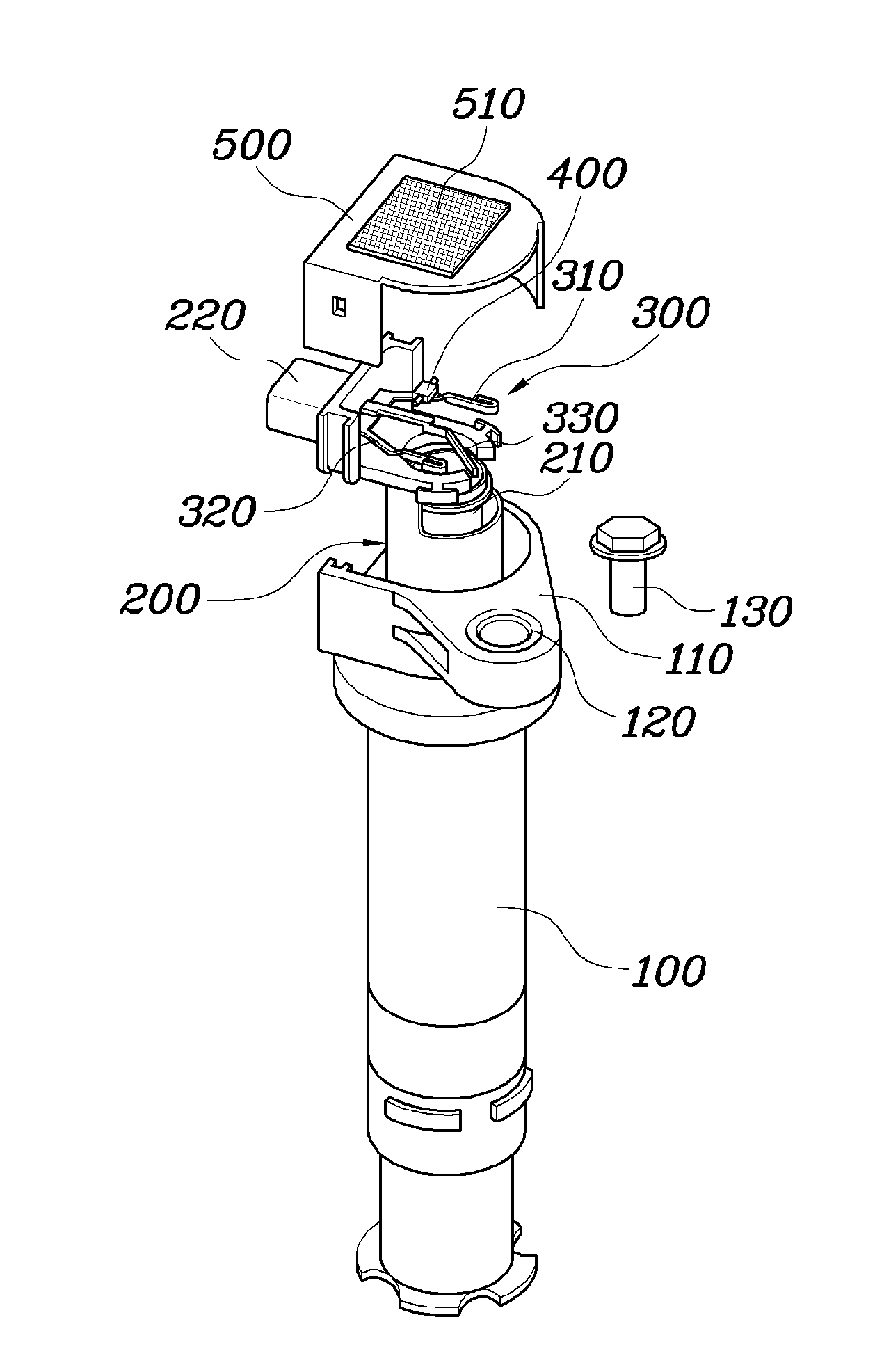
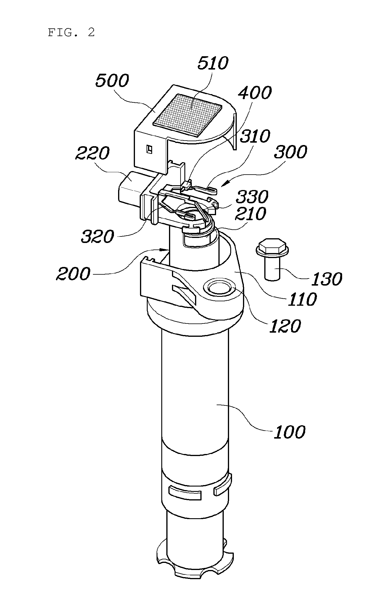
[0010]In certain preferred aspects, the present invention features an ignition coil of an engine, in which a small condenser is directly installed to a low voltage (LV) pin of the ignition coil to effectively remove noise, a cover having waterproof and breathable fiber suitably inserted through insert molding that is suitably applied to dissipate heat from the ignition coil to an outside and suitably prevent the inflow of water, a ground pin is added to the LV pin and the ground pin is suitably connected to a vehicle body or a head cover of the engine to be grounded, thus enhancing the noise removal effect.
[0011]Preferably, in certain embodiments of the present invention, an ignition coil is preferably mounted to a head cover of an engine to supply high voltage to a spark plug in the engine. Preferably, the ignition coil includes an outer casing defining the external appearance of the ignition coil. In certain preferred embodiments, a first spool is inserted into the outer casing, and a second spool is provided in the first spool. Preferably, a LV pin is provided on the upper portion of the first spool. Further, preferably a condenser is provided on the LV pin. Preferably, a cover is provided to cover the upper portion of the outer casing and manufactured through injection molding such that waterproof and breathable fiber dissipating heat from the condenser to an outside and preventing inflow of water from the outside is inserted into the cover.
[0014]As is apparent from the above description, an ignition coil of an engine according to the present invention has certain advantages in that a small condenser is directly installed to an LV pin of the ignition coil to effectively remove noise, a cover having waterproof and breathable fiber (e.g., Gore-Tex) inserted through insert molding is suitably applied to effectively dissipate heat from the ignition coil to an outside and prevent the inflow of water, a ground pin is added to the LV pin and the ground pin is suitably connected to a vehicle body or a head cover of the engine to be grounded, thus suitably enhancing the noise removal effect.

Problems solved by technology

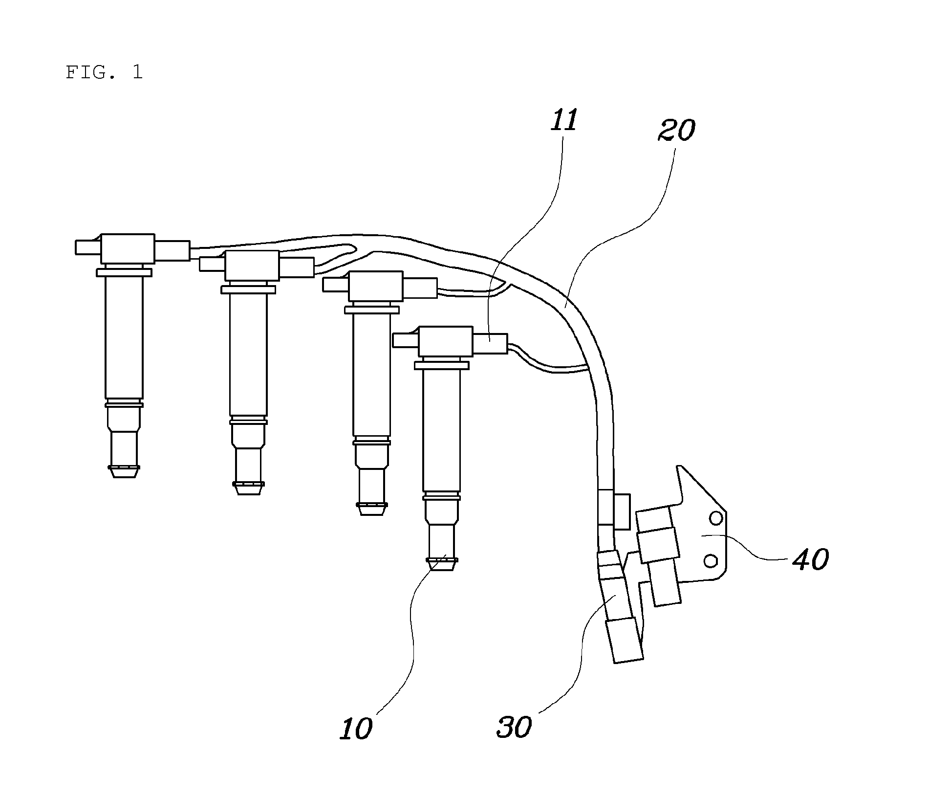
In the conventional condenser, the distance between the ignition coil 10 and the condenser 40 is long, so that it can be difficult to effectively remove noise.

Method used


Image

  • Ignition coil of engine
  • Ignition coil of engine
  • Ignition coil of engine

Examples


Embodiment Construction

[0022]As described herein, the present invention features an ignition coil of an engine comprising an outer casing, first spool inserted into the outer casing, a second spool provided in the first spool, a low voltage (LV) pin, a condenser provided on the LV pin, and a cover provided to cover an upper portion of the outer casing.

[0023]In one preferred embodiment, the ignition coil is mounted to a head cover of the engine to supply high voltage to a spark plug in the engine.

[0024]In another preferred embodiment, the outer casing defines an external appearance of the ignition coil.

[0025]In another further preferred embodiment, a low voltage (LV) pin is provided on an upper portion of the first spool.

[0026]In still another preferred embodiments, the cover is provided to cover an upper portion of the outer casing.

[0027]In one preferred embodiment, the cover is manufactured through injection molding such that waterproof and breathable fiber dissipating heat from the condenser to an outsi...


PUM

PropertyMeasurementUnit
voltageaaaaaaaaaa
distanceaaaaaaaaaa
poweraaaaaaaaaa

Abstract

The present invention features an ignition coil of an engine, in which a small condenser is directly installed to an LV pin of the ignition coil, thus effectively removing noise, and dissipating heat from the ignition coil to an outside, in addition to preventing the inflow of water.

Description

CROSS-REFERENCE TO RELATED APPLICATION[0001]This application claims under 35 U.S.C. §119(a) the benefit of Korean Patent Application No. 10-2009-0117782 filed Dec. 1, 2009, the entire contents of which are incorporated herein by reference.BACKGROUND OF THE INVENTION[0002]1. Field of the Invention[0003]The present invention relates, in general, to ignition coils of engines and, more particularly, to an ignition coil of an engine, which is capable of effectively removing noise from the ignition coil and suitably preventing the inflow of water, in addition to suitably dissipating heat from the ignition coil to an outside.[0004]2. Description of the Related Art[0005]In general, an ignition coil of an engine for a vehicle functions to supply high voltage to spark plugs in the engine, and is mounted to a head cover of the engine and connected to the spark plugs installed in a combustion chamber.[0006]For example, a 4-cylinder engine is described with reference to FIG. 1. Preferably, the 4...

Claims


Application Information

Patent Timeline
Patent Type & Authority Patents(United States)
IPC IPC(8): F02P3/04F02P3/02F02P11/00F02P13/00H01F38/12H01T13/06
CPCH01F38/12F02P11/00F02P13/00H01T13/06F02P3/02
Inventor KIM, JI HYOUNGLEE, JONG WOOKCHO, KYUNG SICKLIM, KI SU
Owner HYUNDAI MOTOR CO LTD
Learn More