Liquid ejecting head and liquid ejecting apparatus

a liquid ejecting apparatus and liquid ejecting technology, which is applied in printing and other directions, can solve the problems of low ejection efficiency, large pressure required, and easy flight deflection, so as to improve liquid repellency, and improve liquid ejection characteristics

Inactive Publication Date: 2014-10-07
SEIKO EPSON CORP
View PDF15 Cites 0 Cited by
  • Summary
  • Abstract
  • Description
  • Claims
  • Application Information

AI Technical Summary

Benefits of technology

[0010]An advantage of some aspects of the invention is to provide a liquid ejecting head and a liquid ejecting apparatus to improve ejection efficiency and liquid ejection characteristics.
[0012]In the liquid ejecting head, since the entire inner wall surface of the first nozzle portion is covered with the liquid repellent film having higher liquid repellency than the base material of the nozzle plate, it is possible to improve pressure applying efficiency. In addition, by covering the entire inner wall surface of the first nozzle portion with the liquid repellent film having higher liquid repellency than the base material of the nozzle plate, a meniscus disposed on the inner wall at the time of ejecting the ink is hardly influenced by the inner wall and flight deflection hardly occurs. Furthermore, since at least a part of the inner wall surface of the second nozzle portion has lower liquid repellency than the liquid repellent film, it is possible to suppress bubbles from adhering. Accordingly, the liquid ejecting head according to the aspect of the invention improves ejection efficiency and liquid ejection characteristics. Here, the liquid repellency means both oil repellency and water repellency for liquid ejected from an ink jet type recording head.
[0013]In the liquid ejecting head, it is preferable that the entire inner wall surface of the second nozzle portion have lower liquid repellency than the liquid repellent film or the liquid repellent film extend to at least a part of the second nozzle portion. With such a configuration, since the liquid repellency of the second nozzle portion is lower than that of the first nozzle portion, it is possible to further suppress bubbles from adhering.
[0018]In the liquid ejecting head, it is preferable that irregularities be formed on the inner wall surface of the first nozzle portion. Due to this, liquid repellency can be improved.
[0019]According to another aspect of the invention, there is provided a liquid ejecting apparatus including the liquid ejecting head according to any of the above-described aspects. By including the liquid ejecting head according to any of the above aspects in which ejection efficiency and liquid ejection characteristics are improved, liquid ejection characteristics are improved.

Problems solved by technology

However, in the structure disclosed in JP-A-2005-161679 (Claim 1 and the like), since the entire inner wall of the nozzle hole is hydrophilic and the inner wall has high wettability for ink.
Therefore there is a problem that a large pressure is required when a meniscus moves in the nozzle hole to a vertical direction at the time of ejecting the ink.
Thus, there is a problem that flight deflection easily occurs.
Thus, it is considerable that a large pressure is required when a meniscus moves in the nozzle hole to the vertical direction at the time of ejecting the ink to lower ejection efficiency and flight deflection occurs and thereby liquid ejection characteristics are lowered.

Method used


Image

  • Liquid ejecting head and liquid ejecting apparatus
  • Liquid ejecting head and liquid ejecting apparatus
  • Liquid ejecting head and liquid ejecting apparatus

Examples


Embodiment Construction

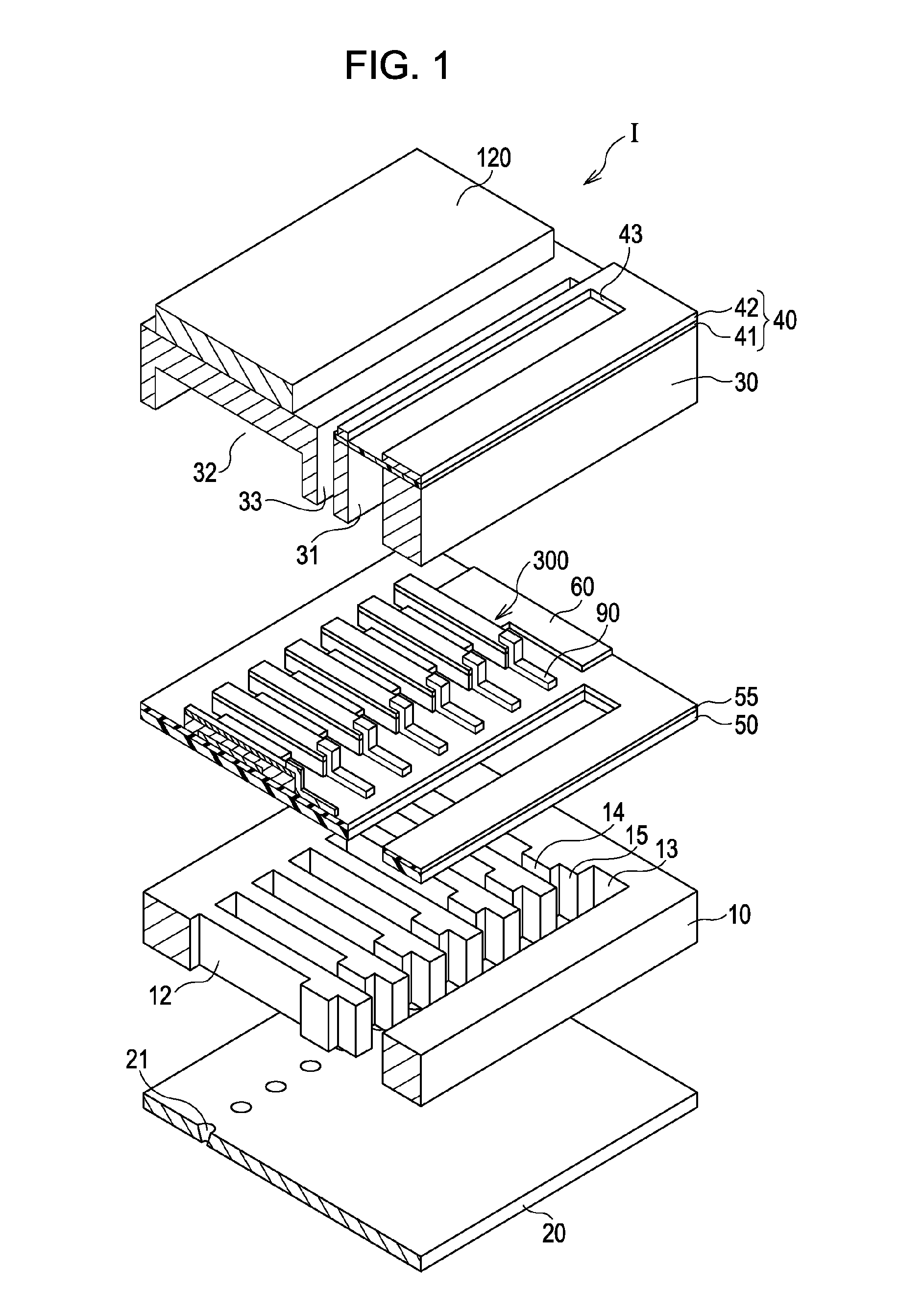
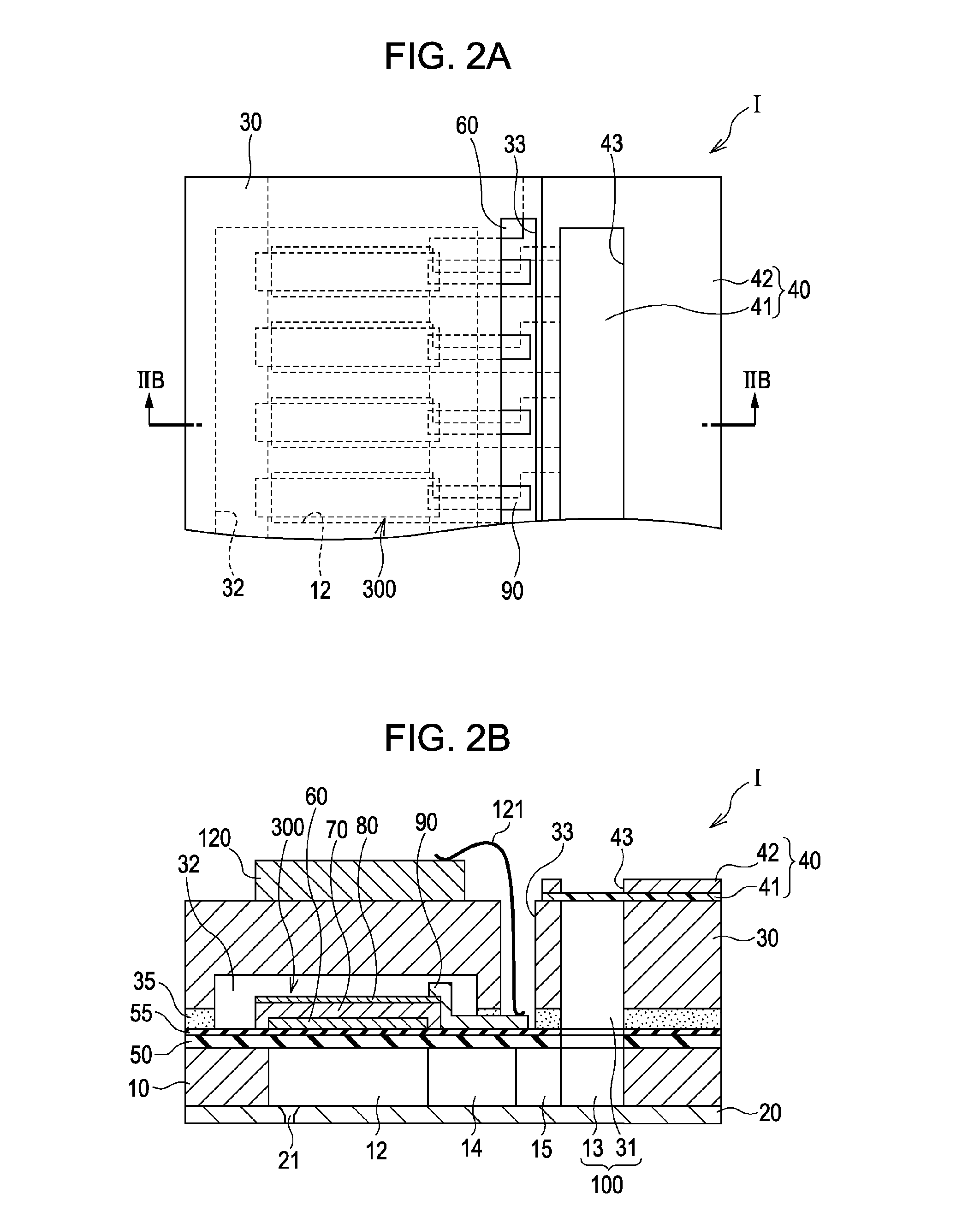
[0031]FIG. 1 is an exploded perspective view showing a schematic configuration of an ink jet type recording head according to a first embodiment of the invention and FIGS. 2A and 2B are a plane view and a cross-sectional view of the recording head 1 cut along a line IIB-IIB.

[0032]As shown in the drawings, a flow path forming substrate 10 is made of a silicon monocrystalline substrate and an elastic film 50 made of is silicon dioxide is formed on one surface thereof.

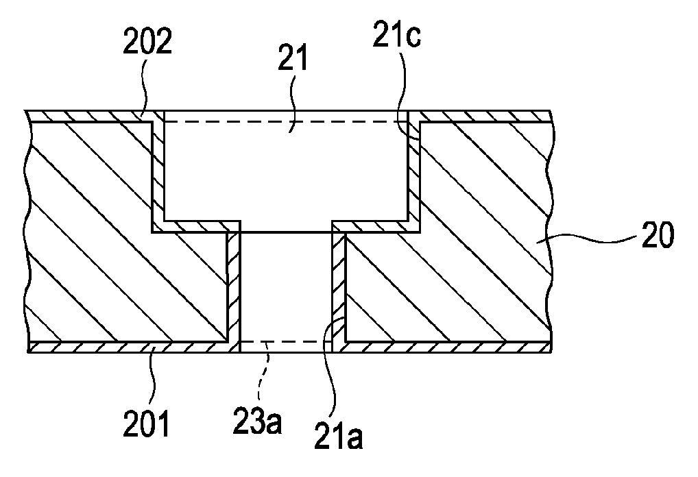
[0033]Plural pressure generating chambers 12 are arranged in the flow path forming substrate 10. In addition, a communicating unit 13 is formed in an outer region in a direction orthogonal to the arranged direction of the pressure generating chambers 12 in the flow path forming substrate 10, and the communicating unit 13 and each pressure generating chamber 12 communicate through an ink supply path 14 and a communication path 15 provided in every pressure generating chamber 12. The communicating unit 13 communicates a man...


PUM


Abstract

The liquid ejecting head includes a nozzle plate in which nozzle holes which are through holes are formed, and ejects liquid from the nozzle holes. The nozzle hole has a first nozzle portion which is opened to an ejection surface to which liquid is ejected from nozzles of the nozzle plate, and a second nozzle portion which communicates with the first nozzle portion, and is opened to a surface opposite to the ejection surface of the nozzle plate, and of which the opening diameter is larger than the opening diameter in the ejection surface of the first nozzle portion. The first nozzle portion is covered with a liquid repellent film which has higher liquid repellency than a base material of the nozzle plate and an inner wall of the second nozzle portion is provided with a region which has lower liquid repellency than the liquid repellent film.

Description

[0001]The entire disclosure of Japanese Patent Application No. 2011-166461, filed Jul. 29, 2011 is incorporated by reference herein.BACKGROUND[0002]1. Technical Field[0003]The present invention relates to a liquid ejecting head and a liquid ejecting apparatus.[0004]2. Related Art[0005]In the related art, as an example of an ink jet type recording head which is a representative example of a liquid ejecting head to eject liquid drops, there is an ink jet type recording head which includes a flow path forming substrate in which plural pressure generating chambers are formed, piezoelectric actuators which are provided to correspond the respective pressure generating chambers on one surface of the flow path forming substrate, and a nozzle plate which is provided on the other surface of the flow path forming substrate and provides nozzle holes to communicate pressure generating chambers, and applies pressure to each pressure generating chamber by displacement of each piezoelectric actuato...

Claims


Application Information

Patent Timeline
Patent Type & Authority Patents(United States)
IPC IPC(8): B41J2/14B41J2/16
CPCB41J2/14233B41J2/1606B41J2/1433
Inventor KATO, JIROASAOKA, ICHIROWADA, MITSUHIRODENDA, SATOSHI
Owner SEIKO EPSON CORP
Why Eureka
Try Eureka