Turbine assembly

a technology of turbines and components, applied in the direction of propellers, propulsive elements, water-acting propulsive elements, etc., can solve the problems of high production costs, time-consuming fitting, and limitations of steam path design, so as to reduce the fitting time and increase the space for additional roots

Active Publication Date: 2014-10-07
GENERAL ELECTRIC TECH GMBH
View PDF26 Cites 7 Cited by
  • Summary
  • Abstract
  • Description
  • Claims
  • Application Information

AI Technical Summary

Benefits of technology

[0011]Another aspect of the present invention relates to the general idea of enabling over-rotation of blade roots in a rotor channel by a combination of radial play of the root foot and neck taper angle of the channel and the root and the parallelogram shape of the platform and / or root. The additional space within the blade row created by the over-rotation increases the space for fitting of additional roots in the channel. In particular, this enables the fitting of a last blade in the blade rows without the need for channel windows. In operation, the roots, by centrifugal forces, are forced radially outwards. In this way, the interaction of the angled root and channel end walls prevents over-rotation and thus the blade roots are circumferentially fixed in the blade row, thus the correct stagger angle is fixed, and over- or under-rotation during operation is prevented. As a result, shims between roots are not required and nor are shrouds that impose torsional bias that prevent rotation, as rotation is not possible. Embodiments can therefore be applied to both shrouded and non-shrouded blades while providing the advantage of significantly reduced blade fitting time, as shims can either be reduced in number or totally eliminated.
[0012]An aspect provides a turbine assembly comprising a rotor and blades. The rotor has a rotational axis, an outer surface, and a channel that is formed in the outer surface circumscribing the rotor. The channel also includes an axially extending foot and a neck portion. The axially extending foot has a base and a radially inward facing land: the radial distance therebetween defines the foot radial height. The neck portion, extending radially between the foot and the outer surface, has a first and a second axial end wall, one or each having a taper angle. In the radial outward direction, this taper angle narrows the neck portion. Located in the channel is a row of circumferentially distributed, rotationally fittable blades. Each blade comprises a root, at least partially located in the channel, that includes an axially extending foot and a neck. The foot has a base and a radial height extending from the base, while the neck, extending radially from the foot, has a first and a second axial end wall. Each of the end walls is tapered to compliment the taper angle, or absence thereof, of the channel neck portion. The shape of the foot and the neck of the root generally compliment the shape of foot and neck of the channel. The radial height of the root foot is less than the radial height of the channel foot. This element together with the taper allows over-rotation of the root in the channel when the roots base is in contact with the channel base, compared to when the root foot is in contact with the channel land, to an extent that enables the fitting of a last blade in the channel root. By this, shims are superfluous. In addition, torsional bias is not required to align and fix the blades as the blades may be fixed merely by operational centrifugal forces.

Problems solved by technology

Each of these configurations requires side access, which, in steam turbines, places limitations on the steam path design.
While this does not require side access, a fitting window in the rotor is required and this window creates a weak point.
A problem with shims is that their production costs are high, partly due to the need for skilled operatives and partly due to the complexity and cost of the shims themselves.
In addition, their fitting demands time, impacting blade assembly and disassembly time.
As it may not be possible to insert the spacer after the fixing of the blades, the solution increases complexity and in addition does not address the problem of circumferential gaps between roots.
The arrangement is, however, limited to assemblies with shrouded blades in which the blade portions are pre-twisted such that, in the final assembled position, radial alignment of the circumferential abutment and the shroud portions provides a torsional bias that maintains the shroud in pressure and frictional contact with its neighbors.
Further, the need to overtwist the shrouds of blades fitted with the described blade roots during fitting in order to create the necessary gap to fit the penultimate blade, in view of the require torsional bias, adds installation complexity and as a result impacts assembly time.
As a result, shims between roots are not required and nor are shrouds that impose torsional bias that prevent rotation, as rotation is not possible.

Method used


Image

  • Turbine assembly
  • Turbine assembly
  • Turbine assembly

Examples


Embodiment Construction

[0020]Preferred embodiments of the present invention are now described with reference to the drawings, wherein like reference numerals are used to refer to like elements throughout. In the following description, for purposes of explanation, numerous specific details are set forth in order to provide a thorough understanding of the disclosure. It may be evident, however, that the disclosure may be practiced without these specific details.

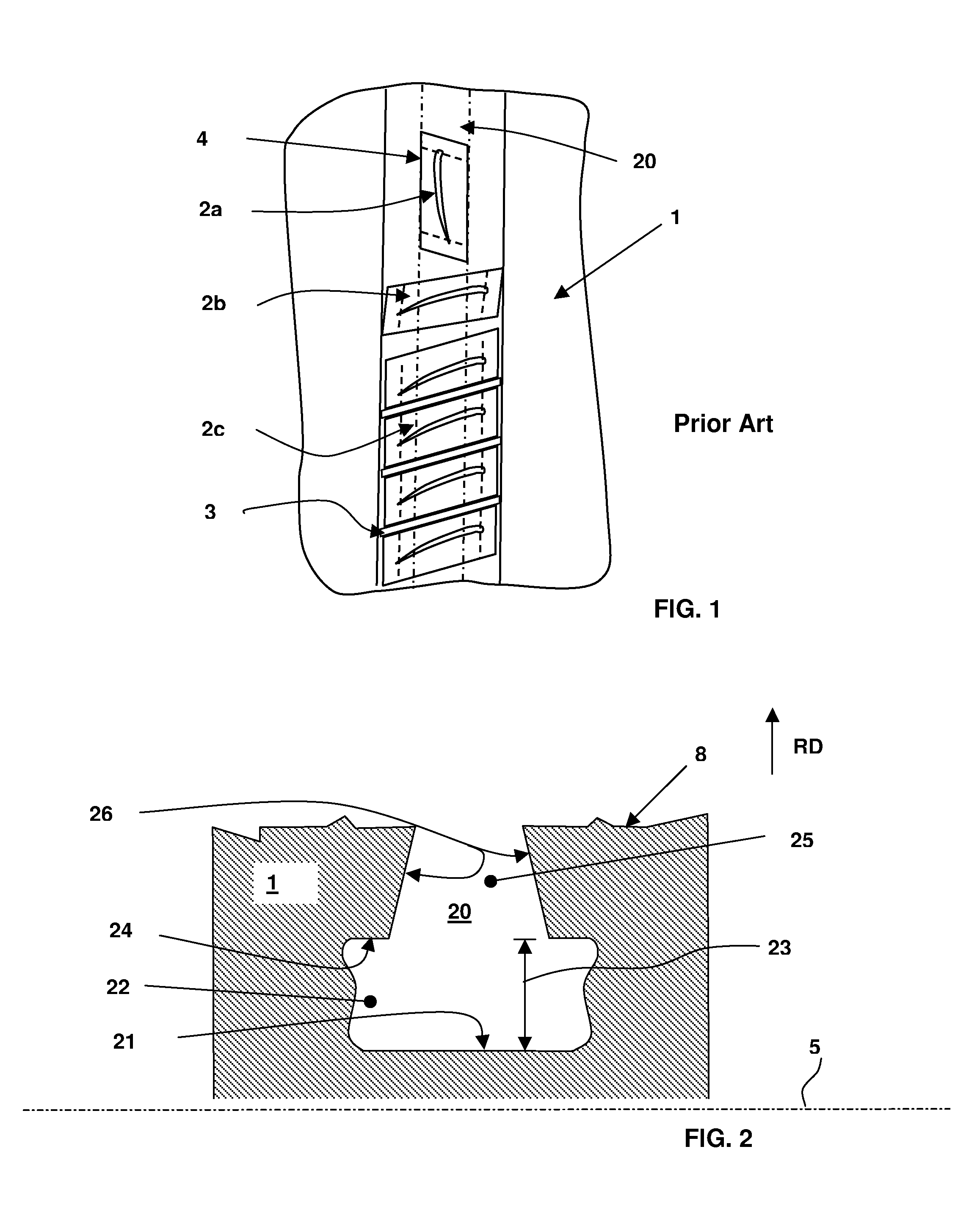
[0021]FIG. 1 shows a prior art blade assembly having blades 2 in various states of being fitted into a rotor 1. Each of the blades 2 has a parallelogram shaped platform and / or root 4 wherein the parallelogram shape allows them to be fitted by over-rotation. The fitting is performed by fitting each blade 2a into the channel of the rotor 20 while other, already fitted blades 2b are over-rotated to provide addition space in the channel 20. Once all blades 2c are fitted, the correct blade stagger angle is achieved by the fitting shims 3 between the blade...


PUM


Abstract

A turbine assembly includes a rotor (1) with a channel (20) and a plurality of blades (10) with a root (30) rotationally fitted in the channel (20). The root (30) and channel (20) have complimentary angled end walls (26, 36) while the root (30) is further configured to have radial play in the channel (20). The combination of this radial play and end wall angle enables, when the base (31) of the root (30) is in contact with the base (21) of the channel (20), enable over-rotating compared to when the base (31) of the root (30) and channel (20) are not in contact. This over-rotation enables the fitting of a last root (30) in the channel (20).

Description

[0001]This application claims priority under 35 U.S.C. §119 to European Application No. 09178147.6, filed 7 Dec. 2009, the entirety of which is incorporated by reference herein.BACKGROUND[0002]1. Field of Endeavor[0003]The disclosure relates generally to turbines and specifically to rotors and rotor blades that are rotationally fitted therein.[0004]2. Brief Description of the Related Art[0005]Known fastening arrangements for fitting blades into rotors to form a blade row include pinned roots and side entry fir trees. Each of these configurations requires side access, which, in steam turbines, places limitations on the steam path design. An alternative structure for fitting blades that does not have this disadvantage uses a so-called straddle root. While this does not require side access, a fitting window in the rotor is required and this window creates a weak point. A yet further blade fitting involves rotational fitting.[0006]Rotationally fitted blades may have either T- or L-shape...

Claims


Application Information

Patent Timeline
Patent Type & Authority Patents(United States)
IPC IPC(8): F01D5/30F01D5/32
CPCF01D5/3038F01D5/32F05D2230/60
Inventor BLATCHFORD, DAVID, PAUL
Owner GENERAL ELECTRIC TECH GMBH
Why Eureka
Try Eureka