Method of capturing satellite signal and device for capturing satellite signal
a satellite signal and signal technology, applied in the field of satellite signal capture, can solve problems such as increasing power consumption
- Summary
- Abstract
- Description
- Claims
- Application Information
AI Technical Summary
Benefits of technology
Problems solved by technology
Method used
Image
Examples
first example
2-1. First Example
2-1-1. Configuration of Mobile Phone
[0071]FIG. 3 is a block diagram showing an example of the functional configuration of a mobile phone 1 of this example. The mobile phone 1 includes a GPS antenna 5, a GPS reception unit 10, a host processing unit 30, an operating unit 40, a display unit 50, a sound output unit 55, a mobile phone antenna 60, a mobile phone wireless communication circuit unit 70, a storage unit 80, and a timepiece unit 90.
[0072]The GPS antenna 5 is an antenna which receives RF (Radio Frequency) signals including GPS satellite signals sent from GPS satellites, and outputs reception signals to the GPS reception unit 10.
[0073]The GPS reception unit 10 is a circuit or a device which calculates the position of the mobile phone 1 on the basis of the signal output from the GPS antenna 5, and corresponds to a so-called GPS receiver. In this embodiment, the GPS reception unit 10 corresponds to a satellite signal capturing device.
[0074]The GPS reception unit...
second example
2-2. Second Example
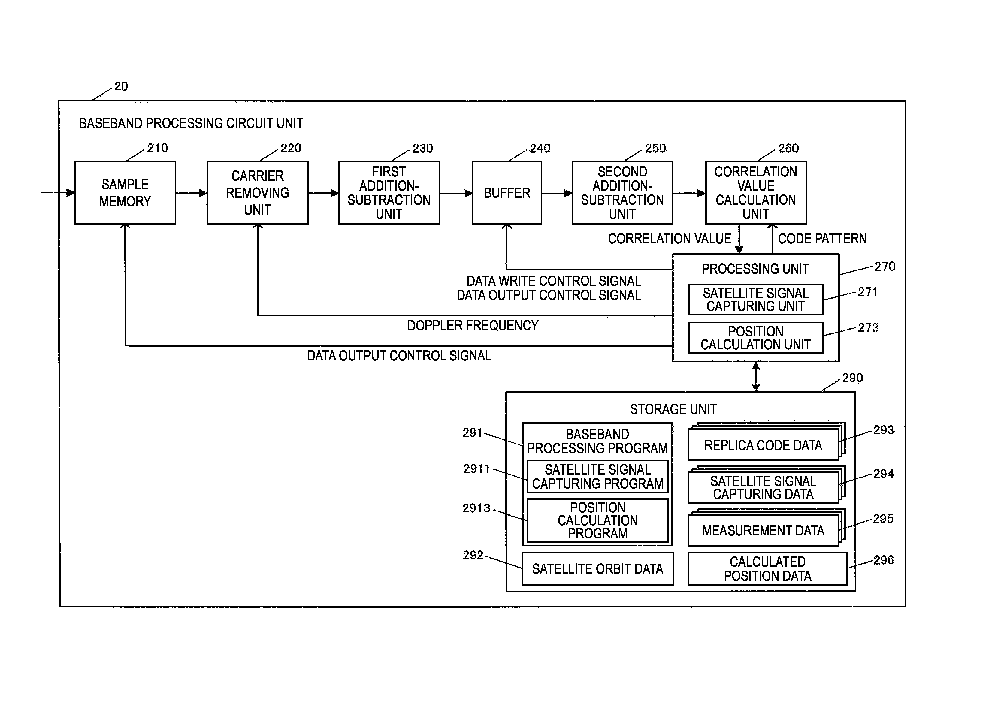
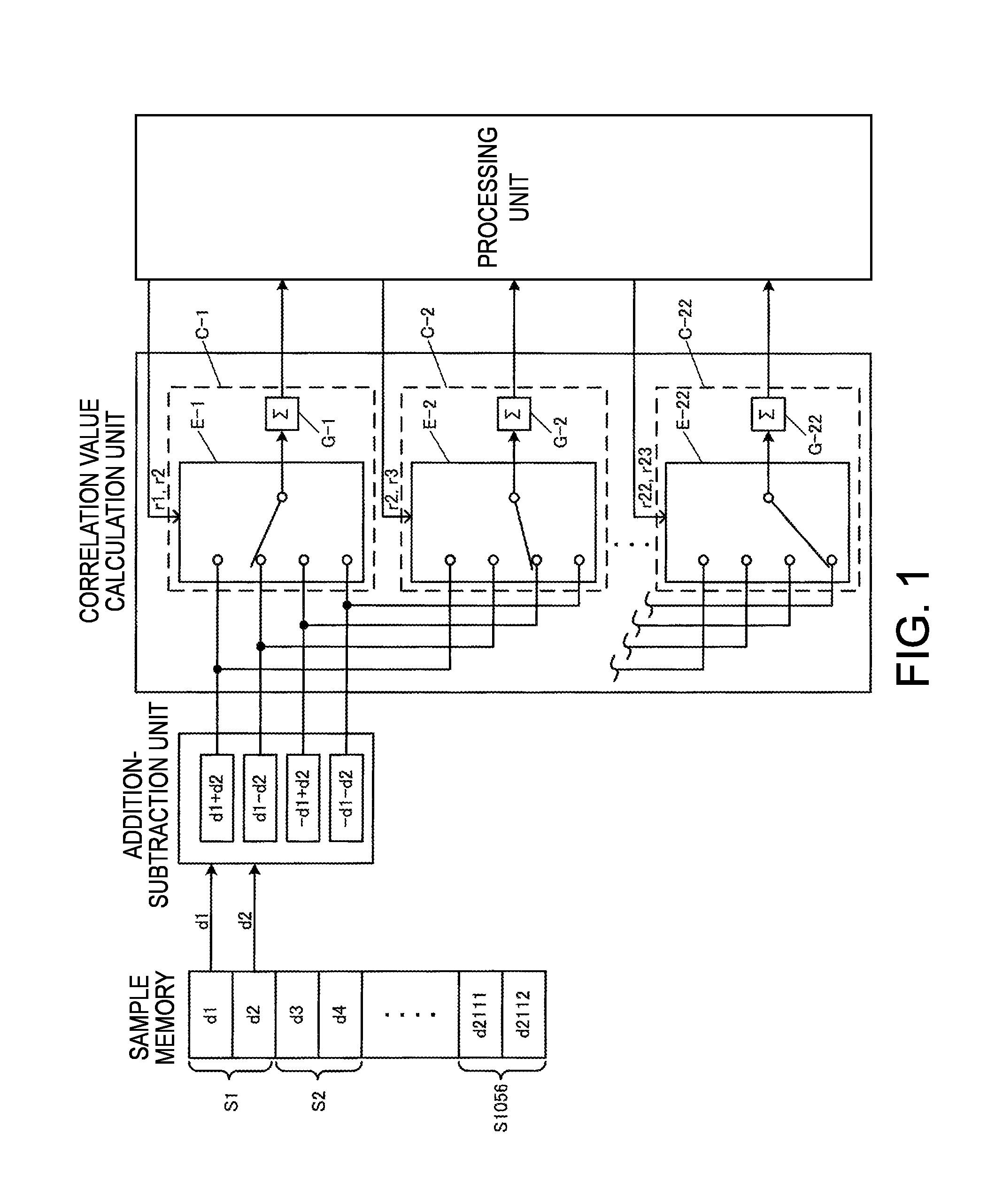
[0137]A second example has a difference from the second addition-subtraction unit in the first example. Specifically, the second addition-subtraction unit is constituted by adder-subtractors in which some of 16 combinations of addition and subtraction are omitted.
[0138]The principle that some of the combinations of addition and subtraction can be omitted will be described with reference to FIG. 9. If replica codes of 1023 chips are sampled 2112 times, two or three sampling values (code values) are included for one chip. If a code pattern of four continuous code values is considered, 16 patterns A to P shown on the lower side of FIG. 9 are considered. However, the patterns I to P are patterns in which the positive and negative signs of the patterns A to H are inverted. Accordingly, the patterns Ito P can be omitted.
[0139]The number of codes included in one chip is not limited to one. That is, a code pattern in which one “+1” is sandwiched between “−1” or a code pat...
PUM
 Abstract
Description
Claims
Application Information
 - R&D
- Intellectual Property
- Life Sciences
- Materials
- Tech Scout
- Unparalleled Data Quality
- Higher Quality Content
- 60% Fewer Hallucinations
Browse by: Latest US Patents, China's latest patents, Technical Efficacy Thesaurus, Application Domain, Technology Topic, Popular Technical Reports.
© 2025 PatSnap. All rights reserved.Legal|Privacy policy|Modern Slavery Act Transparency Statement|Sitemap|About US| Contact US: help@patsnap.com


