Fiber optic connector system

a technology of fiber optic connectors and fiber optic connectors, which is applied in the direction of mechanical equipment, machines/engines, instruments, etc., can solve the problems of insufficient robustness and comparatively complex system types, and achieve the effect of convenient operation

Inactive Publication Date: 2014-10-14
ROBERT BOSCH GMBH
View PDF12 Cites 6 Cited by
  • Summary
  • Abstract
  • Description
  • Claims
  • Application Information

AI Technical Summary

Benefits of technology

[0007]An object of the exemplary embodiments and / or exemplary methods of the present invention is to provide a connector system which protects the optical surfaces of both the plug and the socket from soiling when the connection is open. It is a further aim for the connector system to be easily operable and to withstand the harsh operating conditions in the engine compartment of an internal combustion engine over the entire service life of the vehicle.
[0010]Due to the fact that the plug, as well as the socket which is compatible with the plug, each have a protective sleeve, it is possible to protect the optically active surfaces of the plug and the socket from soiling as soon as the connection is opened.
[0011]By configuring the arrangement according to the exemplary embodiments and / or exemplary methods of the present invention for closing the housing of the plug or of the socket as rotatably mounted flaps, complicated control of the arrangement for closing, with the aid of grooves and sliding elements, may be dispensed with. Furthermore, the protective sleeves may thus be designed to be concentric to the plug and the socket, and for the connector system according to the present invention it is therefore possible for the protective sleeves of the plug and socket to move inside one another in a telescoping manner and to mutually open the flaps of the respective other protective sleeve. As a result, not only is it possible for the plug and socket to automatically close as soon as the connection is separated, but also the optically active surfaces of the plug and socket are automatically exposed again as soon as the connection is re-established by inserting the plug into the socket.
[0012]The at least one flap may be rotatably mounted according to the exemplary embodiments and / or exemplary methods of the present invention on the protective sleeves with the aid of a hinge, in particular a film hinge. When the protective sleeve has two flaps, in one particular embodiment of the present invention it is provided that the rotational axes of the two flaps are parallel. This specific embodiment is particularly suitable when the protective sleeves have a square or rectangular cross section. Namely, in that case it is possible to provide the rotational axes of the flap parallel to two walls of the protective sleeve, so that despite very simple kinematics the entire cross sectional area of the protective sleeves may be closed by one or two flaps, and the protective sleeves of the plug and socket are able to easily move inside one another in a telescoping manner when the connection is established.
[0013]A further advantageous embodiment of the present invention provides that the flaps on the protective sleeves automatically return to a closed position as soon as the connection is separated. This may be easily achieved by providing the hinges with an elastic design.

Problems solved by technology

In laser ignition systems, a pumped light source and an ignition laser are spatially separated from one another because the ignition laser must be situated in the immediate proximity of the combustion chambers of the internal combustion engine, and because the vibrations and operating temperatures of the internal combustion engine have a negative effect on the service life of the pumped light source.
These types of systems are therefore comparatively complex in their manufacture, and do not have the robustness required for operation under harsh conditions in the engine compartment of a motor vehicle.

Method used


Image

  • Fiber optic connector system
  • Fiber optic connector system
  • Fiber optic connector system

Examples


Embodiment Construction

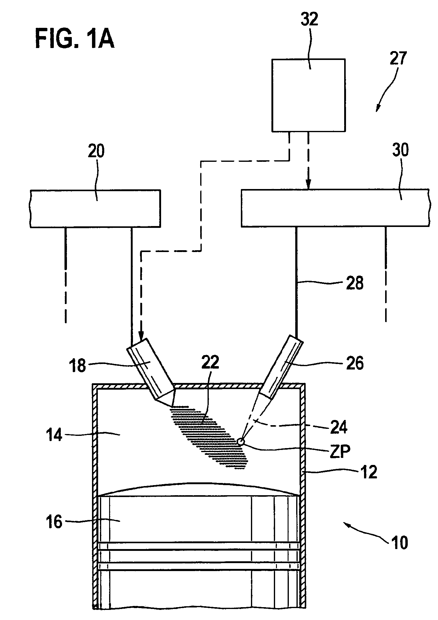
[0029]An internal combustion engine overall is denoted by reference numeral 10 in FIG. 1a. The internal combustion engine may be used to drive a motor vehicle, not illustrated, or a generator for power generation. Internal combustion engine 10 includes multiple cylinders, of which only one is denoted by reference numeral 12 in FIG. 1a. A combustion chamber 14 for cylinder 12 is delimited by a piston 16. In the illustrated exemplary embodiment, fuel passes directly into combustion chamber 14 via an injector 18, which is connected to a fuel pressure accumulator 20, also referred to as a rail. Alternatively, the mixture may be formed in an intake manifold, not illustrated.

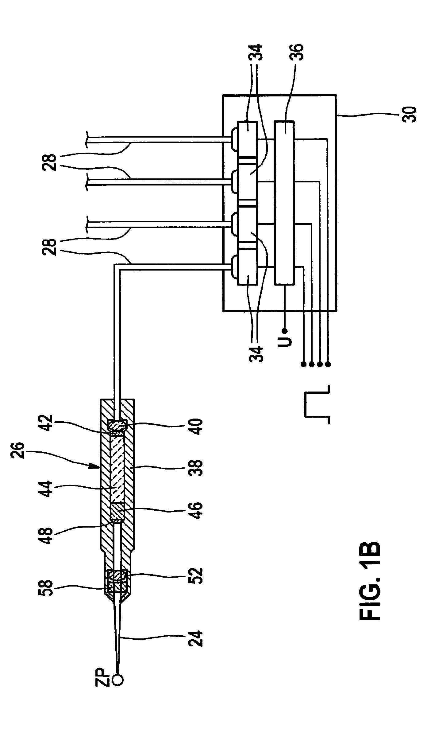
[0030]Fuel 22 injected into combustion chamber 14 or the fuel-air mixture drawn into the combustion chamber is ignited with the aid of a laser pulse 24 which is emitted into combustion chamber 14 by an ignition device 27 which includes an ignition laser 26. For this purpose, laser unit 26 is fed via an optical fiber d...


PUM


Abstract

A fiber optic connector system is described which includes a plug and a socket. The optically active surfaces of the plug and socket are automatically protected from soiling as soon as the connection is opened.

Description

FIELD OF THE INVENTION[0001]The present invention relates to a fiber optic connector system.BACKGROUND INFORMATION[0002]In laser ignition systems, a pumped light source and an ignition laser are spatially separated from one another because the ignition laser must be situated in the immediate proximity of the combustion chambers of the internal combustion engine, and because the vibrations and operating temperatures of the internal combustion engine have a negative effect on the service life of the pumped light source. An optical fiber is present between the pumped light source and the ignition laser to span the distance between the pumped light source and the ignition laser. This optical fiber transports the pumped light generated by the pumped light source to the ignition laser. At that location the actual ignition pulse is generated in a solid-state laser, and is guided into the combustion chamber through a focusing lens and a combustion chamber window. The intended ignition plasm...

Claims


Application Information

Patent Timeline
Patent Type & Authority Patents(United States)
IPC IPC(8): G02B6/42G02B6/36G02B6/00F02P23/04G02B6/38
CPCG02B6/3849G02B6/4292G02B6/3813G02B6/4296F02P23/04
Inventor WEINROTTER, MARTINWOERNER, PASCALRAIMANN, JUERGEN
Owner ROBERT BOSCH GMBH
Why Eureka
Try Eureka