
Disinfection device and method

a disinfection device and technology for bacteria, applied in the field of disinfection devices and methods for bacterial, fungal and/or viral sterilization and disinfection, can solve the problems of high cost, lethal, and common infections, and the renovation of aging hospitals increases and the infection is not easy to spread. , the effect of increasing the risk of airborne fungal and other infections

Active Publication Date: 2014-10-14
UVAS
View PDF11 Cites 31 Cited by
  • Summary
  • Abstract
  • Description
  • Claims
  • Application Information

AI Technical Summary

Benefits of technology

The UV-C area sterilizer effectively disinfects large areas like operating rooms by ensuring a lethal dose of UV-C radiation is evenly distributed, reducing infection risks while being safe for personnel and the environment, with the ability to sanitize or sterilize surfaces within a reasonable time frame.

Problems solved by technology

Nosocomial, or hospital acquired, infections are common, costly, and sometimes lethal.
Renovation of aging hospitals increases risk of airborne fungal and other infections.
Significant morbidity, mortality, and costs are associated with these infections.
Most notably is the overuse of antibiotics and poor personal hygiene such as hand washing.
Abundant evidence exists, however, that the hospital environment itself contributes to the problem by harboring virulent strains of bacteria, fungi, and viruses, and that many methods commonly used are ineffective and may actually spread contaminants.
Topical antiseptics are problematic for several reasons.
First, they have recently been shown to actually induce antibiotic resistances and thus may be adding to the problem.
Secondly, many surfaces such as keyboards, television sets, and monitoring controls are difficult if not impossible to decontaminate with liquid disinfectants without harming the electronics.
Gas disinfection, while effective, is time consuming, hazardous to workers, and environmentally unwise.
The only recent availability of the appropriate bulbs as well as significant safety concerns regarding worker exposure to UV-C likely contribute to the lack of efforts to use UV-C outside of self-contained water purification systems.

Method used


Image

  • Disinfection device and method
  • Disinfection device and method
  • Disinfection device and method

Examples


Embodiment Construction

[0018]The examples given in the discussion of preferred embodiments are fixtures to buildings or rooms to buildings. However, the elements of the device as described herein may also be incorporated in a mobile device that is portable, as described in Deal, U.S. Pat. No. 6,656,424. The power allocation device and method as described herein is useful with fixed and portable devices and methods of ultraviolet-C (UVC) disinfection.

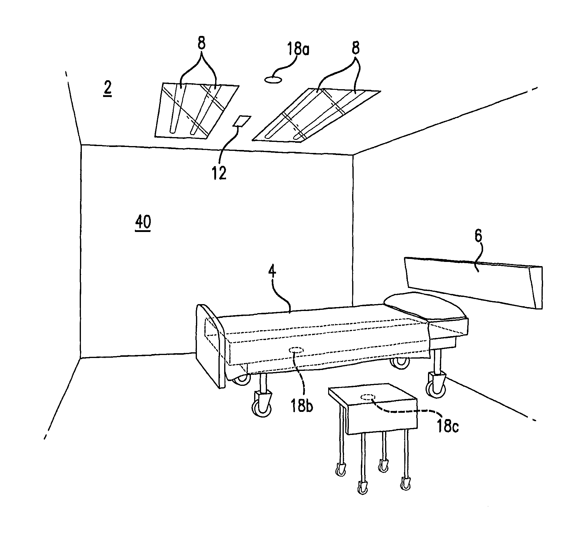
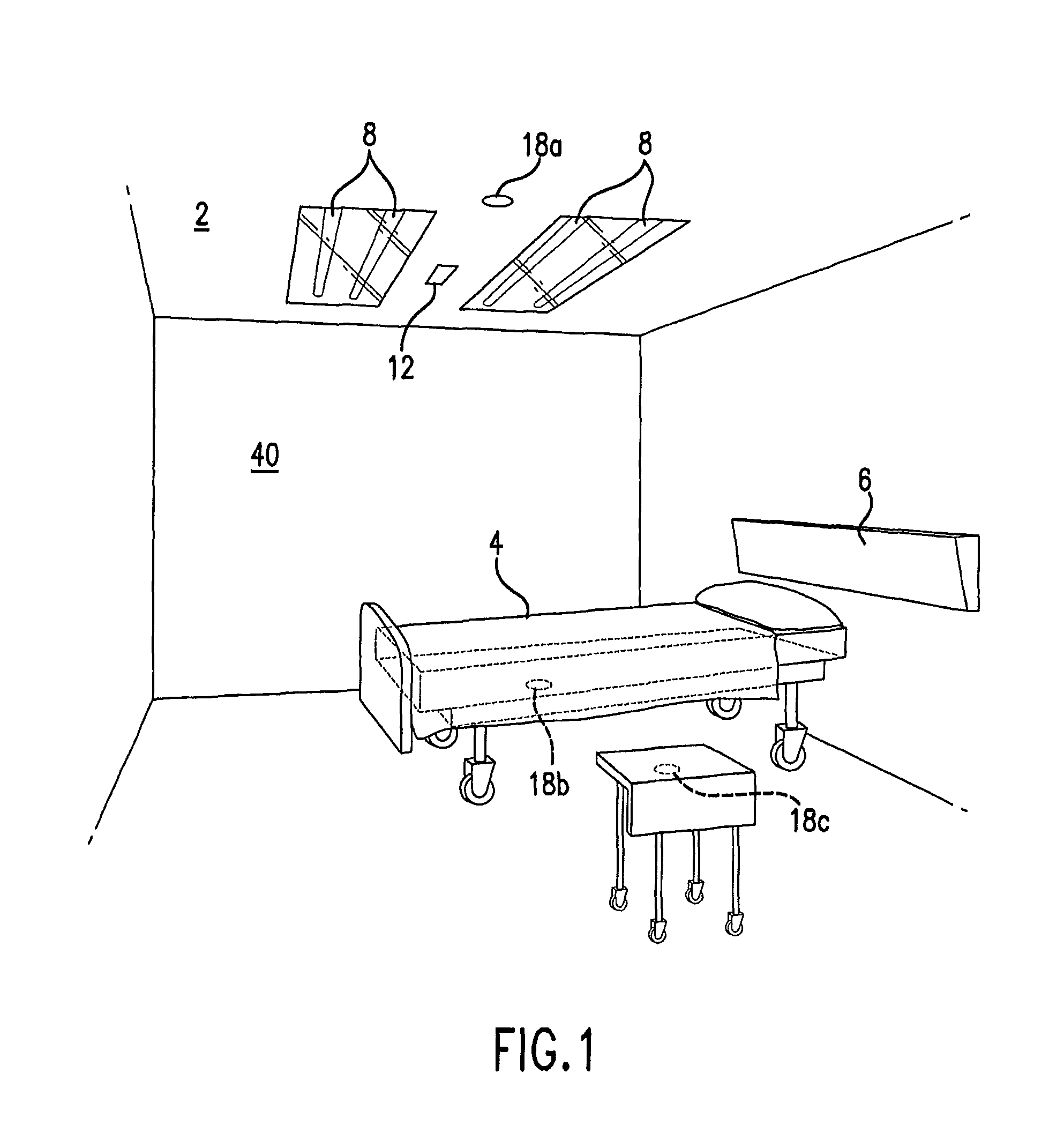
[0019]Referring now to the drawing figures, banks of UV-C emitting bulbs 8 are positioned in an architectural partition, which could be a wall, but may be a ceiling 2 of the enclosed area. The enclosed area may be a room located in a building. FIG. 1.

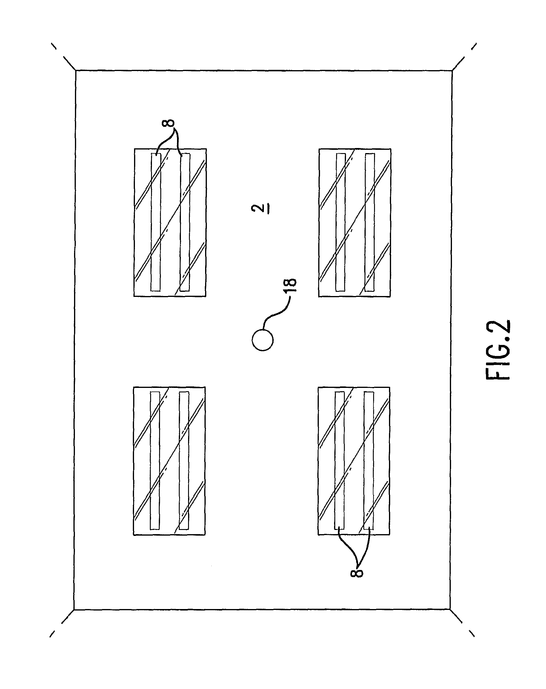
[0020]In one embodiment, four (4) pairs of medium pressure mercury bulbs may be present in a fixture that is located in a ceiling of a room. FIG. 2. The bulbs may be 48-inch long, 115-Watt UV-C generating lamps or bulbs that produce 300 microwatts of ultraviolet radiation at 1 meter. Other effective UV-C generator...


PUM


Abstract

An ultraviolet area sterilizer or disinfector is incorporated into a building structure where concern exists regarding the presence of pathogenic bacteria on environmental surfaces. Ultraviolet C (UV-C) generators generate UV-C that is directed to architectural partitions of an enclosed area. The architectural partitions reflect UV-C to kill pathogens in the enclosed area. The device transmits a calculated dose of UV-C from a fixture mounted to an architectural partition in the enclosed area. Once an effective cumulative dose of UV-C has been reflected to radiation sensors, as measured by the sensors, the device shuts down. The device may allocate power to specific UV-C emitters so as to direct UV-C radiation more uniformly throughout the area, as measured by the sensors.

Description

[0001]This application is a continuation of application Ser. No. 13 / 303,694 filed Nov. 23, 2011, which claims priority from application Ser. No. 12 / 361,810 filed Jan. 29, 2009, now U.S. Pat. No. 8,067,750, issued Nov. 29, 2011, which claims priority from provisional Application Ser. No. 61 / 024,373, filed Jan. 29, 2008; and provisional Application Ser. No. 61 / 083,590, filed Jul. 25, 2008, and in which Applicant claims priority.FIELD OF THE INVENTION[0002]This invention relates to methods and devices for bacterial, fungal and / or viral sterilization and disinfection, and is more particularly directed to a method and device for disinfecting rooms and similar enclosed areas.BACKGROUND OF THE INVENTION[0003]Nosocomial, or hospital acquired, infections are common, costly, and sometimes lethal. A recent review of such infections in the cardiac surgery unit of a major hospital revealed a nosocomial infection rate of 27.3% that more than doubled the mortality rate for afflicted patients. The ...

Claims


Application Information

Patent Timeline
Patent Type & Authority Patents(United States)
IPC IPC(8): G21K5/02A61L9/20A61L2/10A61L2/08
CPCA61L2202/14A61L2209/111A61L9/20A61L2/10A61L2202/25A61L2/08H05B37/0272A61L2202/11H05B37/0227H05B37/0254G01J1/429A61L2/24H05B47/18H05B47/19H05B47/115Y02B20/40
Inventor DEAL, JEFFERY, L.
Owner UVAS
Learn More